LTC1443/LTC1444/LTC1445
3
144345fe
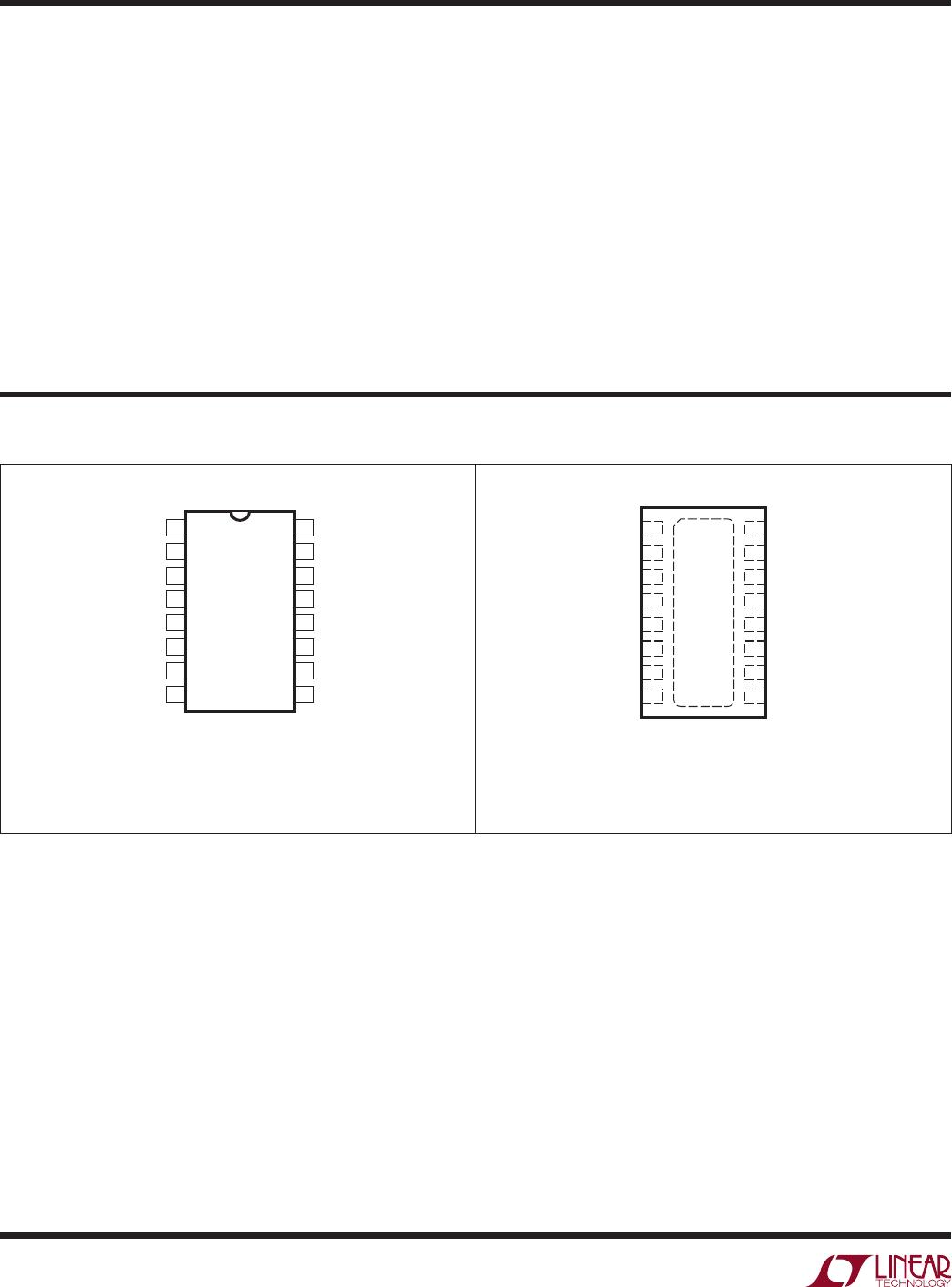
orDer inForMaTion
LEAD FREE FINISH TAPE AND REEL PART MARKING* PACKAGE DESCRIPTION
SPECIFIED
TEMPERATURE RANGE
LTC1443CN#PBF LTC1443CN#TRPBF LTC1443CN 16-Lead PDIP 0°C to 70°C
LTC1443CS#PBF LTC1443CS#TRPBF LTC1443CS 16-Lead Plastic SO 0°C to 70°C
LTC1443IN#PBF LTC1443IN#TRPBF LTC1443IN 16-Lead PDIP –40°C to 85°C
LTC1443IS#PBF LTC1443IS#TRPBF LTC1443IS 16-Lead Plastic SO –40°C to 85°C
LTC1444CN#PBF LTC1444CN#TRPBF LTC1444CN 16-Lead PDIP 0°C to 70°C
LTC1444CS#PBF LTC1444CS#TRPBF LTC1444CS 16-Lead Plastic SO 0°C to 70°C
LTC1444IN#PBF LTC1444IN#TRPBF LTC1444IN 16-Lead PDIP –40°C to 85°C
LTC1444IS#PBF LTC1444IS#TRPBF LTC1444IS 16-Lead Plastic SO –40°C to 85°C
LTC1445CN#PBF LTC1445CN#TRPBF LTC1445CN 16-Lead PDIP 0°C to 70°C
LTC1445CS#PBF LTC1445CS#TRPBF LTC1445CS 16-Lead Plastic SO 0°C to 70°C
LTC1445IN#PBF LTC1445IN#TRPBF LTC1445IN 16-Lead PDIP –40°C to 85°C
LTC1445IS#PBF LTC1445IS#TRPBF LTC1445IS 16-Lead Plastic SO –40°C to 85°C
LTC1443CDHD#PBF LTC1443CDHD#TRPBF 1443 16-Lead (5mm × 4mm) Plastic DFN 0°C to 70°C
LTC1443IDHD#PBF LTC1443IDHD#TRPBF 1443 16-Lead (5mm × 4mm) Plastic DFN –40°C to 85°C
LTC1444CDHD#PBF LTC1444CDHD#TRPBF 1444 16-Lead (5mm × 4mm) Plastic DFN 0°C to 70°C
LTC1444IDHD
#PBF LTC1444IDHD#TRPBF
1444 16-Lead (5mm × 4mm) Plastic DFN –40°C to 85°C
LTC1445CDHD#PBF LTC1445CDHD#TRPBF 1445 16-Lead (5mm × 4mm) Plastic DFN 0°C to 70°C
LTC1445IDHD#PBF LTC1445IDHD#TRPBF 1445 16-Lead (5mm × 4mm) Plastic DFN –40°C to 85°C
Consult LTC Marketing for parts specified with wider operating temperature ranges. *The temperature grade is identified by a label on the shipping container.
Consult LT C Marketing for information on nonstandard lead based finish parts.
For more information on lead free part marking, go to: http://www.linear.com/leadfree/
For more information on tape and reel specifications, go to: http://www.linear.com/tapeandreel/
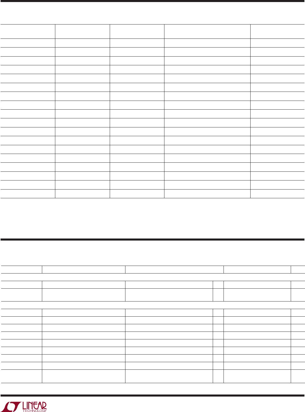
SYMBOL PARAMETER CONDITIONS MIN TYP MAX UNITS
Power Supply
V
+
Supply Voltage Range
l
2.0 11.0 V
I
CC
Supply Current IN
+
= IN
–
= 80mV
HYST = REF (LTC1444/LTC1445)
l
5.5 8.5 µA
Comparator
V
OS
Comparator Input Offset Voltage V
CM
= 2.5V
l
±3.0 ±10.0 mV
I
IN
Input Leakage Current (IN
+
, IN
–
) V
IN
+
= V
IN
–
= 2.5V
l
±0.01 ±1.0 nA
Input Leakage Current (HYST) LTC1444/LTC1445
l
±0.02 ±1.0 nA
V
CM
Comparator Input Common Mode Range
l
V
–
V
+
– 1.3V V
CMRR Common Mode Rejection Ratio V
–
to (V
+
– 1.3V) 0.1 1.0 mV/V
PSRR Power Supply Rejection Ratio V
+
= 2V to 11V 0.1 1.0 mV/V
Noise Voltage Noise 100Hz to 100kHz 20 µV
RMS
V
HYST
Hysteresis Input Voltage Range LTC1444, LTC1445
l
REF – 50mV REF V
t
PD
Propagation Delay Overdrive = 10mV, C
OUT
= 100pF
Overdrive = 100mV, C
OUT
= 100pF
12
4
µs
µs
The l denotes the specifications which apply over the full operating
temperature range, otherwise specifications are at T
A
= 25°C. V
+
= 5V, V
–
= GND = 0V, unless otherwise noted.
elecTrical characTerisTics