MARCH 3, 2017 27 PROGRAMMABLE CLOCK GENERATOR
5P49V5901 DATASHEET
Table 26 Nominal Voltage Divider Values vs Driver VDD
shows resistor values that ensure the maximum drive level for
the CLKIN port is not exceeded for all combinations of 5%
tolerance on the driver VDD, the VersaClock Vddo_0 and 5%
resistor tolerances. The values of the resistors can be
adjusted to reduce the loading for slower and weaker
LVCMOS driver by increasing the impedance of the R1-R2
divider. To assist this assessment, the total load on the driver
is included in the table.
Table 26: Nominal Voltage Divider Values vs Driver VDD
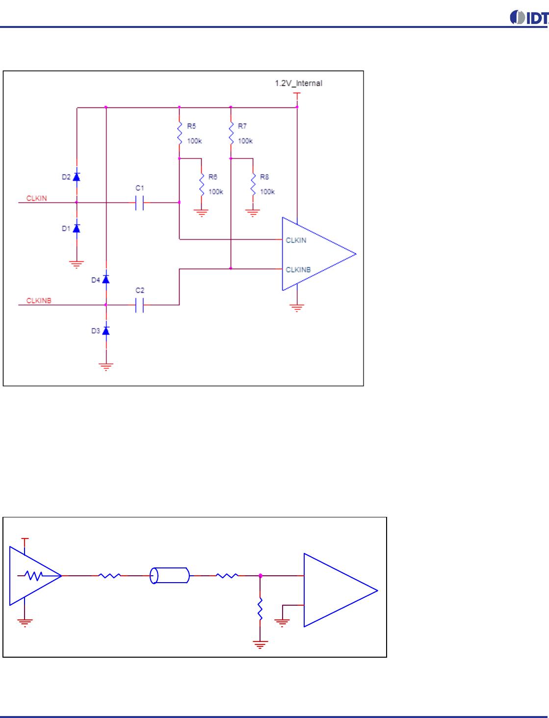
HCSL Differential Clock Input Interface
CLKIN/CLKINB will accept DC coupled HCSL signals.
CLKIN, CLKINB Input Driven by an HCSL Driver
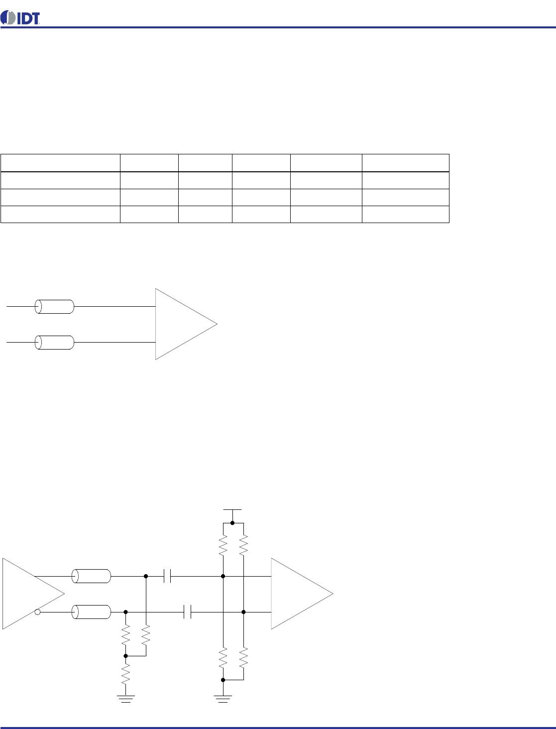
3.3V Differential LVPECL Clock Input Interface
The logic levels of 3.3V LVPECL and LVDS can exceed VIH
max for the CLKIN/B pins. Therefore the LVPECL levels must
be AC coupled to the VersaClock differential input and the DC
bias restored with external voltage dividers. A single table of
bias resistor values is provided below for both for 3.3V
LVPECL and LVDS. Vbias can be VDDD, V
DDOX
or any other
available voltage at the VersaClock receiver that is most
conveniently accessible in layout.
CLKIN, CLKINB Input Driven by a 3.3V LVPECL Driver
LVCMOS Driver VDD Ro+Rs R1 R2 Vrx (peak) Ro+Rs+R1+R2
3.3 50.0 130 75 0.97 255
2.5 50.0 100 100 1.00 250
1.8 50.0 62 130 0.97 242
Zo=50ohm
Zo=50ohm
CLKIN
CLKINB
VersaClock 5 Receiver
Q
nQ
+3.3V LVPECL
Driver
Zo=50ohm
Zo=50ohm
VersaClock 5 Receiver
R9 R10
50ohm
50ohm
Vbias
Rpu1 Rpu2
CLKIN
CLKINB
RTT
50ohm
C5
0.01µF
C6
0.01µF
R15
4.7kohm
R13
4.7kohm