LTC4219
13
4219fd
For more information www.linear.com/LTC4219
applicaTions inFormaTion
1.235V for a minimum of 5µs and then low will clear the
fault latch. If the TIMER pin is tied to INTV
CC
then the
switch is allowed to turn on again (after an internal 100ms
delay), if the overcurrent fault latch is cleared.
Tying the P-channel MOSFET Q1 to the EN1 pin allows
the part to self-clear the fault and turn the MOSFET on as
soon as the TIMER pin has ramped below 0.21V. In the
auto-retry mode the LTC4219 repeatedly tries to turn on
after an overcurrent at a period determined by the capaci
-
tor on the TIMER pin. The auto-retry mode also functions
when the TIMER pin is tied to INT
V
CC
.
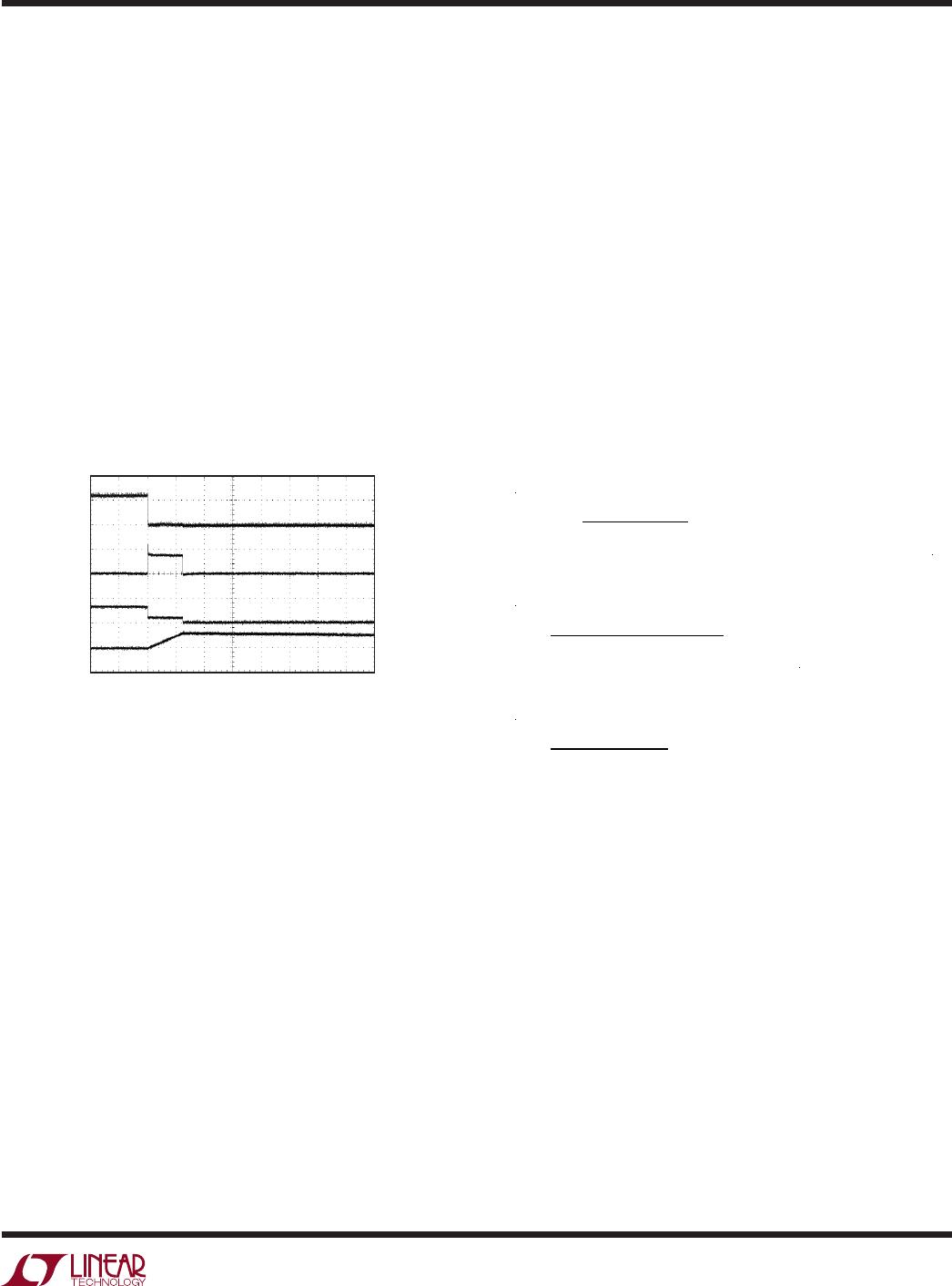
The waveform in Figure 4 shows how the output latches
off following a short-circuit. The current in the MOSFET
is 1.4A as the timer ramps up.
The overall current limit threshold precision is reduced to
±12% when using a 20k resistor to halve the threshold.
Using a switch (connected to ground) in series with R
SET
allows the active current limit to change only when the
switch is closed. This feature can be used to program a
reduced running current while the maximum available
current limit is used at startup.
Monitor MOSFET Temperature
The voltage at the I
SET
pin increases linearly with increas-
ing temperature. The temperature profile of the I
SET
pin is
shown in the Typical Performance Characteristics section.
Using a comparator or ADC to measure the I
SET
voltage
provides an indicator of the MOSFET temperature.
The I
SET
voltage follows the formula:
V
ISET
=
SET
R
SET
+R
ISET
• (T+ 273°C) • 2.093[mV/°C]
The MOSFET temperature is calculated using R
ISET
of 20k.
T =
SET
+
ISET
R
• 2.093[mV/°C]
− 273°C
when R
SET
is not present, T becomes:
T =
ISET
2.093[mV/°C]
− 273°C
There is an overtemperature circuit in the LTC4219 that
monitors an internal voltage similar to the I
SET
pin voltage.
When the die temperature exceeds 145°C the circuit turns
off the MOSFET until the temperature drops to 125°C.
Monitor MOSFET Current
The current in the MOSFET passes through an internal
7.5mΩ sense resistor. The voltage on the sense resistor is
converted to a current that is sourced out of the I
MON
pin.
The gain of I
SENSE
amplifier is 20µA/A referenced from the
MOSFET current. This output current can be converted to
a voltage using an external resistor to drive a comparator
or ADC. The voltage compliance for the I
MON
pin is from
0V to INTV
CC
– 0.7V.
Figure 4. Short-Circuit Waveform
AV
GATE
10V/DIV
I
OUT
2A/DIV
V
OUT
10V/DIV
TIMER
2V/DIV
1ms/DIV
4219 F04
Current Limit Adjustment
The default value of the active current limit is 5.6A. The
current limit threshold can be adjusted lower by placing
a resistor between the I
SET
pin and ground. As shown in
the Functional Block Diagram the voltage at the I
SET
pin
(via the clamp circuit) sets the CS amplifier’s built-in offset
voltage. This offset voltage directly determines the active
current limit value. With the I
SET
pin open, the voltage at
the I
SET
pin is determined by a positive temperature co-
efficient reference. This voltage is set to 0.618V at room
temperature which corresponds to a 5.6
A current limit at
room temperature.
An external resistor R
SET
placed between the I
SET
pin and
ground forms a resistive divider with the internal 20k R
ISET
sourcing resistor. The divider acts to lower the voltage at
the I
SET
pin and therefore lower the current limit threshold.