Features
■ Fast switching
■ Automatic reset
■ SMA package
■ Suitable for industrial lighting environments
■ RoHS compliant*
Applications
■ LED streetlights
■ LCD backlighting
■ Display lighting
■ Intrinsically safe lighting
Absolute Maximum Ratings (@ T
A
= 25 °C Unless Otherwise Noted)
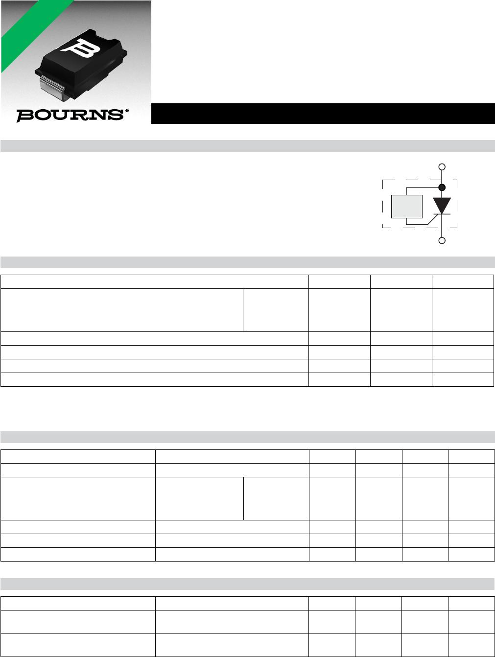
LSPxxxxAJR Series LED Shunt Protector
JANUARY 2012 – REVISED FEBRUARY 2012
*RoHS Directive 2002/95/EC Jan. 27, 2003 including annex and RoHS Recast 2011/65/EU June 8, 2011.
Specifi cations are subject to change without notice.
Customers should verify actual device performance in their specifi c applications.
General Information
Bourns
®
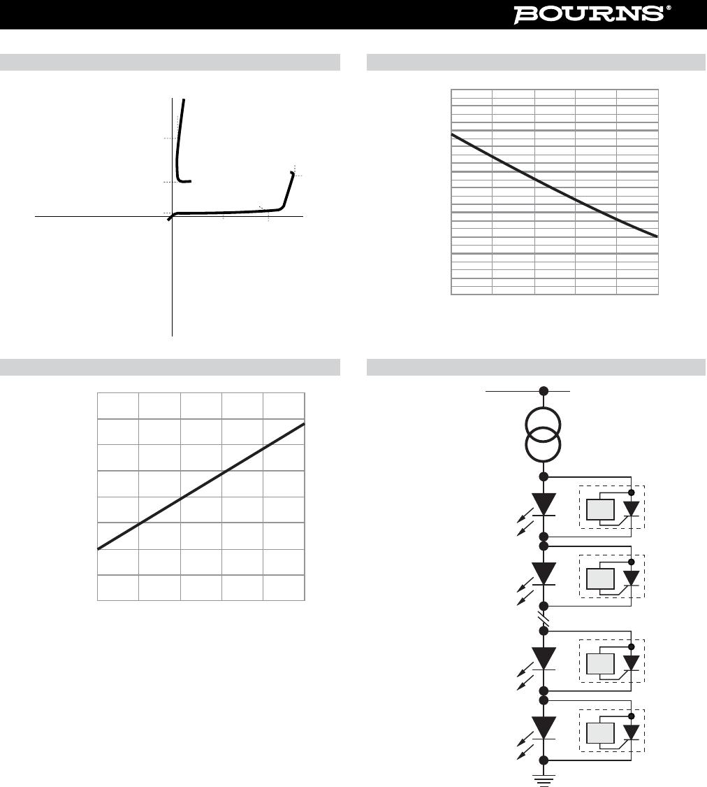
LSP Series protectors are electronic shunts that provide a current bypass
when an LED element in an LED series string fails open circuit. This ensures the
remaining string of LEDs will continue to function. There are many cases where high
reliability of the LED lighting must be maintained, such as LCD backlighting, transport
lighting, avionics, intrinsically safe and low maintenance lighting.
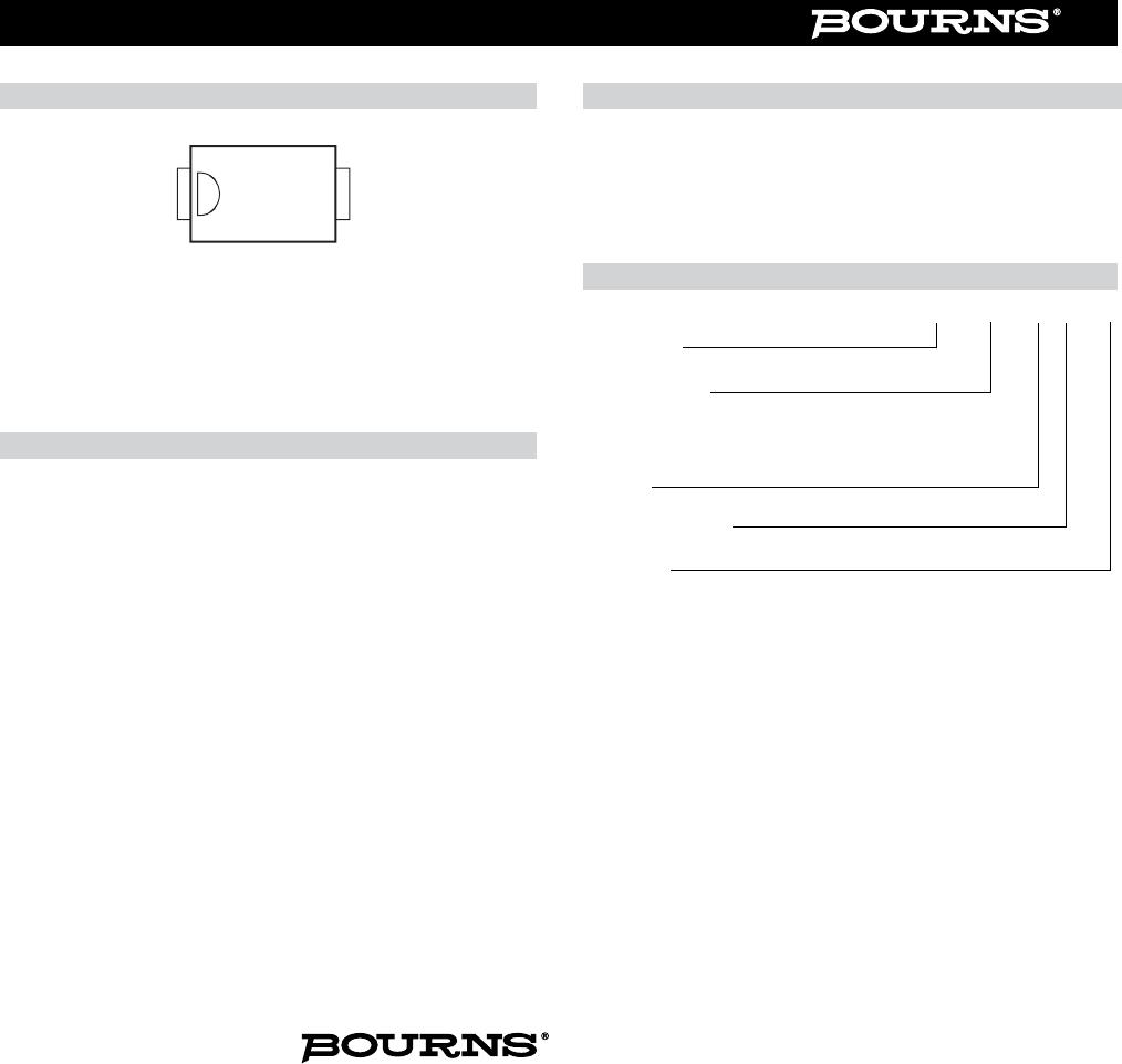
The LSPxxxAJR Series is available in surface mount package DO-214AC (SMA) size
format.
Rating Symbol Value Unit
Repetitive peak off-state voltage
LSP0600
LSP0900
LSP1300
LSP1800
V
DRM
6
9
13
18
V
Average on-state current (Note 1) I
T
1A
Operating junction temperature T
J
-40 to +150 °C
Storage temperature T
s
-65 to +150 °C
Lead temperature, soldering (10 s) 260 °C
Electrical Characteristics (@ T
A
= 25 °C Unless Otherwise Noted)
Parameter Test Conditions Min. Nom. Max. Unit
I
DRM
Repetitive peak off-state current V
D
= V
DRM
10 µA
V
(BO)
Breakover voltage
dv/dt = 750 V/ms,
R
SOURCE
= 300
LSP0600
LSP0900
LSP1300
LSP1800
6
9
13
18
16
18
26
33
V
I
H
Holding current I
T
= 1 A, di/dt = 30 mA/ms 5 30 mA
I
BO
Breakover current di/dt = 0.8 A/ms 75 mA
V
T
On-state voltage I
T
= 1 A 1.2 V
Anode
Cathode
Control
Circuit
LSPxx00
Notes:
1. Using 75 mm x 75 mm 4-Layer PCB (EIA/JESD51-7).
Thermal Characteristics (@ T
A
= 25 °C Unless Otherwise Noted)
Parameter Test Conditions Min. Nom. Max. Unit
Junction to free air thermal resistance
EIA/JESD51-3 PCB, I
T
= 350 mA,
T
A
= 25 °C
230 °C/W
Junction to free air thermal resistance
EIA/JESD51-7, 75 mm x 75 mm 4-Layer
PCB, I
T
= 1.0 A, T
A
= 25 °C
90 °C/W
*RoHS COMPLIANT