1.5SMC82CA-M3/57T

1.5SMC Series
www.vishay.com
Vishay General Semiconductor
Revision: 11-Oct-16
1
Document Number: 88303
For technical questions, contact: DiodesAmericas@vishay.com
THIS DOCUMENT IS SUBJECT TO CHANGE WITHOUT NOTICE. THE PRODUCTS DESCRIBED HEREIN AND THIS DOCUMENT
ARE SUBJECT TO SPECIFIC DISCLAIMERS, SET FORTH AT www.vishay.com/doc?91000
Surface Mount TRANSZORB
®
Transient Voltage Suppressors
DEVICES FOR BI-DIRECTION APPLICATIONS
For bi-directional devices use CA suffix (e.g.
1.5SMC220CA).
Electrical characteristics apply in both directions.
FFEATURES
Low profile package
Ideal for automated placement
Glass passivated chip junction
Available in uni-directional and bi-directional
1500 W peak pulse power capability with a
10/1000 μs waveform, repetitive rate (duty cycle): 0.01 %
Excellent clamping capability
Very fast response time
Low incremental surge resistance
Meets MSL level 1, per J-STD-020, LF maximum peak of
260 °C
AEC-Q101 qualified
Material categorization: for definitions of compliance
please see www.vishay.com/doc?99912
TYPICAL APPLICATIONS
Use in sensitive electronics protection against voltage
transients induced by inductive load switching and lightning
on ICs, MOSFET, signal lines of sensor units for consumer,
computer, industrial, automotive, and telecommunication.
MECHANICAL DATA
Case: DO-214AB (SMC)
Molding compound meets UL 94 V-0 flammability rating
Base P/N-E3 - RoHS compliant and industrial grade
Base P/NHE3_X - RoHS-compliant and AEC-Q101 qualified
(“_X” denotes revision code e.g. A, B, .....)
Terminals: Matte tin plated leads, solderable per
J-STD-002 and JESD 22-B102
E3 suffix meets JESD 201 class 2 whisker test, HE3 suffix
meets JESD 201 class 2 whisker test
Polarity: For uni-directional types the band denotes
cathode end, no marking on bi-directional types
Notes
(1)
Non-repetitive current pulse, per fig. 3 and derated above T
A
= 25 °C per fig. 2.
(2)
Mounted on 0.31" x 0.31" (8.0 mm x 8.0 mm) copper pads to each terminal
PRIMARY CHARACTERISTICS
V
WM
5.8 V to 459 V
V
BR
(uni-directional) 6.8 V to 540 V
V
BR
(bi-directional) 6.8 V to 220 V
P
PPM
1500 W
P
D
6.5 W
I
FSM
(uni-directional only) 200 A
T
J
max. 150 °C
Polarity Uni-directional, bi-directional
Package DO-214AB (SMC)
DO-214AB (SMC)
MAXIMUM RATINGS (T
A
= 25 °C unless otherwise noted)
PARAMETER SYMBOL VALUE UNIT
Peak power dissipation with a 10/1000 μs waveform
(1)(2)
(fig. 1) P
PPM
1500 W
Peak pulse current with a 10/1000 μs waveform
(1)
(fig. 3) I
PPM
See next table A
Power dissipation on infinite heatsink at T
A
= 50 °C P
D
6.5 W
Peak forward surge current 8.3 ms single half sine-wave uni-directional only
(2)
I
FSM
200 A
Operating junction and storage temperature range T
J
, T
STG
-65 to +150 °C
1.5SMC Series
www.vishay.com
Vishay General Semiconductor
Revision: 11-Oct-16
2
Document Number: 88303
For technical questions, contact: DiodesAmericas@vishay.com
THIS DOCUMENT IS SUBJECT TO CHANGE WITHOUT NOTICE. THE PRODUCTS DESCRIBED HEREIN AND THIS DOCUMENT
ARE SUBJECT TO SPECIFIC DISCLAIMERS, SET FORTH AT www.vishay.com/doc?91000
Notes
(1)
Pulse test: t
p
50 ms
(2)
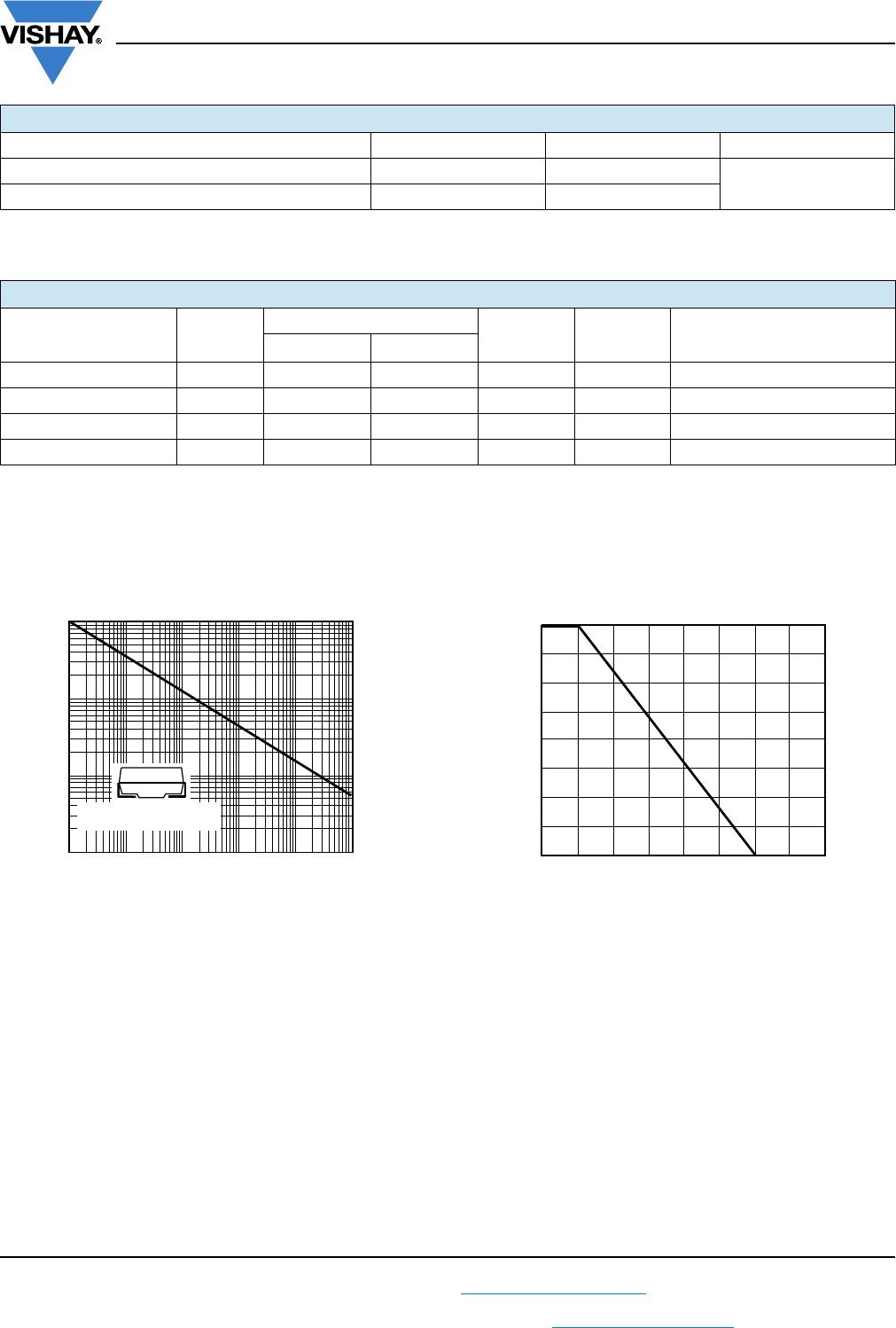
Surge current waveform per fig. 3 and derate per fig. 2
(3)
All terms and symbols are consistent with ANSI/IEEE CA62.35
(4)
For bi-directional types with V
R
of 10 V and less, the I
D
limit is doubled
(5)
V
F
= 3.5 V at I
F
= 100 A (uni-directional only)
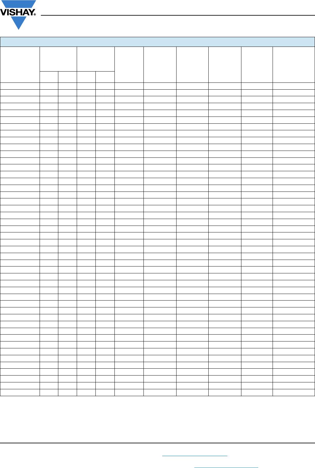
ELECTRICAL CHARACTERISTICS (T
A
= 25 °C unless otherwise noted)
PART
NUMBER
DEVICE
MARKING
CODE
BREAKDOWN
VOLTAGE
V
BR
AT I
T
(1)
(V)
TEST
CURRENT
I
T
(mA)
STAND-OFF
VOLTAGE
V
WM
(V)
MAXIMUM
REVERSE
LEAKAGE
AT V
WM
I
D
(4)
(μA)
MAXIMUM
PEAK
PULSE
CURRENT
I
PPM
(2)
(A)
MAXIMUM
CLAMPING
VOLTAGE
AT I
PPM
V
C
(V)
MAXIMUM
TEMPERATURE
COEFFICIENT
OF V
BR
(%/°C)
UNI BI MIN. MAX.
1.5SMC6.8A 6V8A 6V8C 6.45 7.14 10 5.80 1000 143 10.5 0.057
1.5SMC7.5A 7V5A 7V5C 7.13 7.88 10 6.40 500 133 11.3 0.061
1.5SMC8.2A 8V2A 8V2C 7.79 8.61 10 7.02 200 124 12.1 0.065
1.5SMC9.1A 9V1A 9V1C 8.65 9.55 1.0 7.78 50 112 13.4 0.068
1.5SMC10A 10A 10C 9.50 10.5 1.0 8.55 10 103 14.5 0.073
1.5SMC11A 11A 11C 10.5 11.6 1.0 9.40 5.0 96.2 15.6 0.075
1.5SMC12A 12A 12C 11.4 12.6 1.0 10.2 5.0 89.8 16.7 0.078
1.5SMC13A 13A 13C 12.4 13.7 1.0 11.1 5.0 82.4 18.2 0.081
1.5SMC15A 15A 15C 14.3 15.8 1.0 12.8 1.0 70.8 21.2 0.084
1.5SMC16A 16A 16C 15.2 16.8 1.0 13.6 1.0 66.7 22.5 0.086
1.5SMC18A 18A 18C 17.1 18.9 1.0 15.3 1.0 59.5 25.2 0.089
1.5SMC20A 20A 20C 19.0 21.0 1.0 17.1 1.0 54.2 27.7 0.090
1.5SMC22A 22A 22C 20.9 23.1 1.0 18.8 1.0 49.0 30.6 0.092
1.5SMC24A 24A 24C 22.8 25.2 1.0 20.5 1.0 45.2 33.2 0.090
1.5SMC27A 27A 27C 25.7 28.4 1.0 23.1 1.0 40.0 37.5 0.096
1.5SMC30A 30A 30C 28.5 31.5 1.0 25.6 1.0 36.2 41.4 0.097
1.5SMC33A 33A 33C 31.4 34.7 1.0 28.2 1.0 32.8 45.7 0.098
1.5SMC36A 36A 36C 34.2 37.8 1.0 30.8 1.0 30.1 49.9 0.099
1.5SMC39A 39A 39C 37.1 41.0 1.0 33.3 1.0 27.8 53.9 0.100
1.5SMC43A 43A 43C 40.9 45.2 1.0 36.8 1.0 25.3 59.3 0.101
1.5SMC47A 47A 47C 44.7 49.4 1.0 40.2 1.0 23.1 64.8 0.101
1.5SMC51A 51A 51C 48.5 53.6 1.0 43.6 1.0 21.4 70.1 0.102
1.5SMC56A 56A 56C 53.2 58.8 1.0 47.8 1.0 19.5 77.0 0.103
1.5SMC62A 62A 62C 58.9 65.1 1.0 53.0 1.0 17.6 85.0 0.104
1.5SMC68A 68A 68C 64.6 71.4 1.0 58.1 1.0 16.3 92.0 0.104
1.5SMC75A 75A 75C 71.3 78.8 1.0 64.1 1.0 14.6 104 0.105
1.5SMC82A 82A 82C 77.9 86.1 1.0 70.1 1.0 13.3 113 0.105
1.5SMC91A 91A 91C 86.5 95.5 1.0 77.8 1.0 12.0 125 0.106
1.5SMC100A 100A 100C 95.0 105 1.0 85.5 1.0 10.9 137 0.106
1.5SMC110A 110A 110C 105 116 1.0 94.0 1.0 9.9 152 0.107
1.5SMC120A 120A 120C 114 126 1.0 102 1.0 9.1 165 0.107
1.5SMC130A 130A 130C 124 137 1.0 111 1.0 8.4 179 0.107
1.5SMC150A 150A 150C 143 158 1.0 128 1.0 7.2 207 0.106
1.5SMC160A 160A 160C 152 168 1.0 136 1.0 6.8 219 0.108
1.5SMC170A 170A 170C 162 179 1.0 145 1.0 6.4 234 0.108
1.5SMC180A 180A 180C 171 189 1.0 154 1.0 6.1 246 0.108
1.5SMC200A 200A 200C 190 210 1.0 171 1.0 5.5 274 0.108
1.5SMC220A 220A 220C 209 231 1.0 185 1.0 4.6 328 0.108
1.5SMC250A 250A - 237 263 1.0 214 1.0 4.4 344 0.110
1.5SMC300A 300A - 285 315 1.0 256 1.0 3.6 414 0.110
1.5SMC350A 350A - 333 368 1.0 300 1.0 3.1 482 0.110
1.5SMC400A 400A - 380 420 1.0 342 1.0 2.7 548 0.110
1.5SMC440A 440A - 418 462 1.0 376 1.0 2.5 602 0.110
1.5SMC480A 480A - 456 504 1.0 408 1.0 2.28 658 0.110
1.5SMC510A 510A - 485 535 1.0 434 1.0 2.15 698 0.110
1.5SMC540A 540A - 513 567 1.0 459 1.0 2.03 740 0.110
1.5SMC Series
www.vishay.com
Vishay General Semiconductor
Revision: 11-Oct-16
3
Document Number: 88303
For technical questions, contact: DiodesAmericas@vishay.com
THIS DOCUMENT IS SUBJECT TO CHANGE WITHOUT NOTICE. THE PRODUCTS DESCRIBED HEREIN AND THIS DOCUMENT
ARE SUBJECT TO SPECIFIC DISCLAIMERS, SET FORTH AT www.vishay.com/doc?91000
Note
(1)
Mounted on minimum recommended pad layout
Note
(1)
AEC-Q101 qualified
RATINGS AND CHARACTERISTICS CURVES (T
A
= 25 °C unless otherwise noted)
Fig. 1 - Peak Pulse Power Rating Curve Fig. 2 - Pulse Power or Current vs. Initial Junction Temperature
THERMAL CHARACTERISTICS (T
A
= 25 °C unless otherwise noted)
PARAMETER SYMBOL VALUE UNIT
Typical thermal resistance, junction to ambient air
(1)
R
JA
75
°C/ W
Typical thermal resistance, junction to leads R
JL
15
ORDERING INFORMATION (Example)
PREFERRED P/N
UNIT
WEIGHT
(g)
VOLTAGE RANGE (V)
PACKAGE
CODE
BASE
QUANTITY
DELIVERY MODE
UNI - BI -
1.5SMC6.8A-E3/57T 0.211 6.8 to 540 6.8 to 220 57T 850 7" diameter plastic tape and reel
1.5SMC6.8A-E3/9AT 0.211 6.8 to 540 6.8 to 220 9AT 3500 13" diameter plastic tape and reel
1.5SMC250AHE3_A/H
(1)
0.211 250 to 540 - H 850 7" diameter plastic tape and reel
1.5SMC250AHE3_A/I
(1)
0.211 250 to 540 - I 3500 13" diameter plastic tape and reel
0.1
1
10
100
0.31 x 0.31" (8.0 x 8.0 mm)
Copper Pad Areas
0.1 µs 1.0 µs 10 µs 100 µs 1.0 ms 10 ms
P
PPM
- Peak Pulse Power (kW)
t
d
- Pulse Width (s)
0 25 50 75 100
100
75
50
25
0
125 150 175 200
T
J
- Initial Temperature (°C)
Peak Pulse Power (P
PP
) or Current (I
PP
)
Derating in Percentage, %

1.5SMC82CA-M3/57T

Mfr. #:
Manufacturer:
Vishay
Description:
TVS Diodes - Transient Voltage Suppressors 1.5KW,82V 5%,BIDIR,SMC TVS
Lifecycle:
New from this manufacturer.
Delivery:
DHL FedEx Ups TNT EMS
Payment:
T/T Paypal Visa MoneyGram Western Union