8
FN6867.2
January 14, 2010
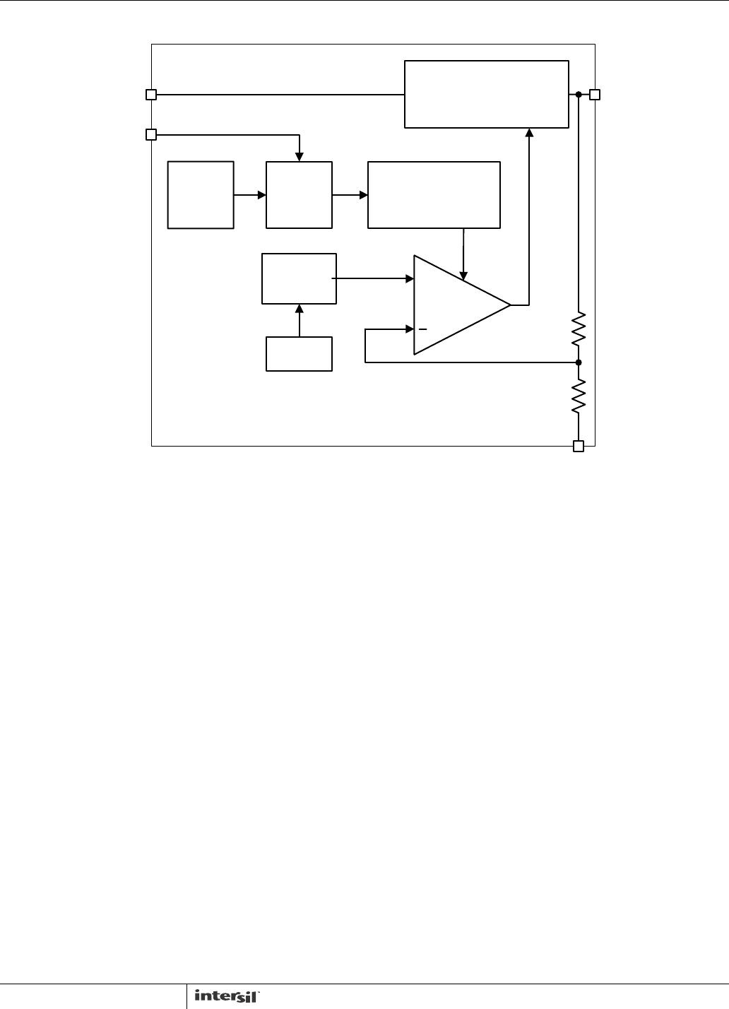
Functional Description
The ISL9021 is a high performance low-dropout regulator
(LDO) with 250mA sourcing capability. The extra low ground
current makes this part a good choice for handheld product
applications. The device also incorporates overcurrent,
thermal shutdown, reverse current protections, and soft-start
features.
Thermal shutdown protects the device against overheating.
Soft-start limits the start-up input current surges. In some
applications, the output voltage may be externally pulled
higher than input, or the input voltage could be connected to
ground, or connected to some voltage lower than the output
side. The ISL9021 features reverse current protection; that
can block the reverse current from output to input.
Enable Control
The ISL9021 has an enable pin. When EN is low, the IC is in
shutdown mode. In this condition, all on-chip circuits are off,
and the device draws minimum current, typically less than
0.1µA(typ). Driving this pin high will turn on the device.
LDO Protections
The ISL9021 offers several protection functions, making it ideal
for use in battery-powered applications.The ISL9021 provides
short-circuit protection by limiting the output current at current
limit of 260mA(min). If the short circuit lasts long enough, the
die temperature increases, and the over-temperature protection
circuit will shut down the output. When the die temperature
reaches about +145°C, thermal protection starts to work with
output being loaded with at least 50mA. Once the die
temperature drops to about +110°C, the LDO will resume
operation beginning with a soft-start.
The ISL9021’s reverse current protection is intended to
block reverse conduction if output voltage is higher than
input voltage.
Input and Output Capacitors
The ISL9021 provides a linear regulator that has low
quiescent current, fast transient response, and overall stable
operation across the recommended operating conditions. A
ceramic capacitor (X5R or X7R) with a capacitance of 1µF to
4.7µF with an ESR up to 400mΩ is suitable for the ISL9021
to maintain its output stability. The ground connection of the
output capacitor should be routed directly to the GND pin of
the device, and also placed close to the IC. Similarly for the
input capacitor, usually a 1µF ceramic capacitor (X5R or 7R)
is suitable for most cases, but if a large, fast rising load
transient condition is expected, a higher value input
capacitor may be necessary to achieve satisfactory
performance.
Board Layout Recommendations
A good PCB layout is an important step to achieve good
performance. It is recommended to design the board with
separate ground planes for input and output, and connect
both ground planes at the GND pin of the IC. Consideration
should be taken when placing the components and routing
the trace to minimize the ground impedance, and keep the
parasitic inductance low. Usually the input/output capacitors
should be placed as close to the IC as possible with a good
ground connection.
ISL9021