MURS160T3G

© Semiconductor Components Industries, LLC, 2017
April, 2017 Rev. 15
1 Publication Order Number:
MURS120T3/D
MURS120T3G Series,
SURS8120T3G Series,
NRVUS120VT3G Series
Surface Mount
Ultrafast Power Rectifiers
MURS105T3G, MURS110T3G, MURS115T3G,
MURS120T3G, MURS140T3G, MURS160T3G,
SURS8105T3G, SURS8110T3G, SURS8115T3G,
SURS8120T3G, SURS8140T3G, SURS8160T3G,
NRVUS110VT3G, NRVUS120VT3G,
NRVUS160VT3G
Ideally suited for high voltage, high frequency rectification, or as
free wheeling and protection diodes in surface mount applications
where compact size and weight are critical to the system.
Features
Small Compact Surface Mountable Package with JBend Leads
Rectangular Package for Automated Handling
High Temperature Glass Passivated Junction
Low Forward Voltage Drop (0.71 to 1.05 V Max @ 1.0 A, T
J
= 150°C)
NRVUS and SURS8 Prefixes for Automotive and Other Applications
Requiring Unique Site and Control Change Requirements;
AECQ101 Qualified and PPAP Capable
These Devices are PbFree, Halogen Free/BFR Free and are RoHS
Compliant
Mechanical Characteristics:
Case: Epoxy, Molded
Weight: 95 mg (Approximately)
Finish: All External Surfaces Corrosion Resistant and Terminal
Leads are Readily Solderable
Lead and Mounting Surface Temperature for Soldering Purposes:
260°C Max. for 10 Seconds
Polarity: Polarity Band Indicates Cathode Lead
ESD Rating:
Human Body Model = 3B (> 8 kV)
Machine Model = C (> 400 V)
See detailed ordering and shipping information in the table on
page 2 of this data sheet.
ORDERING INFORMATION
MARKING DIAGRAM
See general marking information in the device marking table
on page 2 of this data sheet.
DEVICE MARKING INFORMATION
ULTRAFAST RECTIFIERS
1.0 AMPERE, 50600 VOLTS
SMB
CASE 403A
www.onsemi.com
A = Assembly Location*
Y = Year
WW = Work Week
U1 = Device Code
x = A, B, C, D, G, or J
G =PbFree Package
AYWW
U1x G
G
(Note: Microdot may be in either location)
* The Assembly Location code (A) is front side
optional. In cases where the Assembly Location is
stamped in the package bottom (molding ejecter
pin), the front side assembly code may be blank.
MURS120T3G Series, SURS8120T3G Series, NRVUS120VT3G Series
www.onsemi.com
2
MAXIMUM RATINGS
Rating Symbol
MURS/SURS8/NRVUS
Unit
105T3 110T3
115T3 120T3 140T3 160T3
Peak Repetitive Reverse Voltage
Working Peak Reverse Voltage
DC Blocking Voltage
V
RRM
V
RWM
V
R
50 100 150 200 400 600 V
Average Rectified Forward Current I
F(AV)
1.0 @ T
L
= 155°C
2.0 @ T
L
= 145°C
1.0 @ T
L
= 150°C
2.0 @ T
L
= 125°C
A
NonRepetitive Peak Surge Current, (Surge applied
at rated load conditions halfwave, single phase, 60 Hz)
I
FSM
40 35 A
Operating Junction Temperature T
J
*65 to +175 °C
Stresses exceeding those listed in the Maximum Ratings table may damage the device. If any of these limits are exceeded, device functionality
should not be assumed, damage may occur and reliability may be affected.
THERMAL CHARACTERISTICS
Rating Symbol
MURS/SURS8/NRVUS
Unit
105T3 110T3
115T3 120T3 140T3 160T3
Thermal Resistance
JunctiontoLead (T
L
= 25°C)
R
q
JL
13
°C/W
ELECTRICAL CHARACTERISTICS
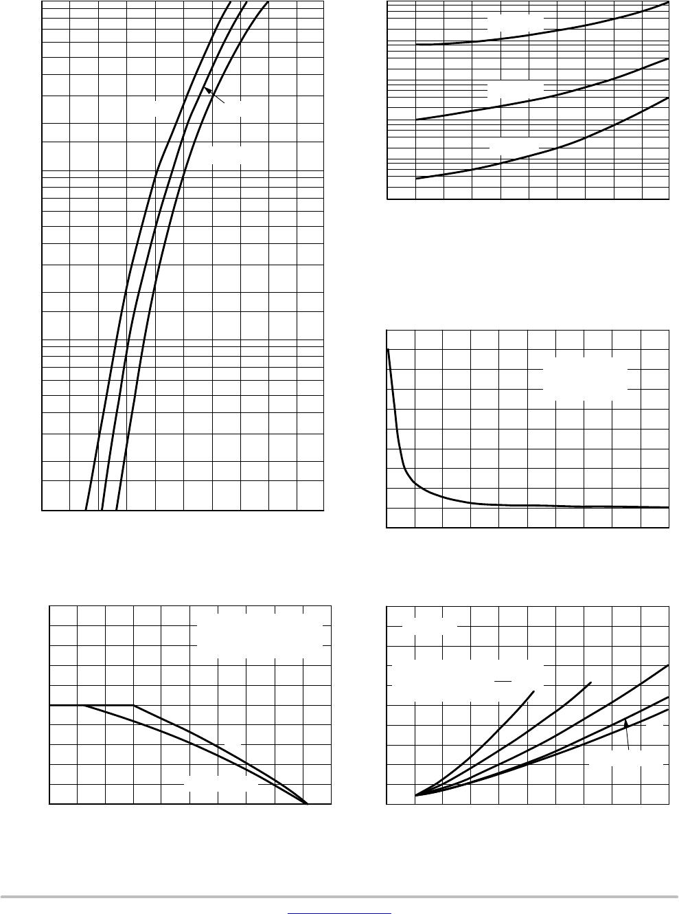
Maximum Instantaneous Forward Voltage (Note 1)
(i
F
= 1.0 A, T
J
= 25°C)
(i
F
= 1.0 A, T
J
= 150°C)
v
F
0.875
0.71
1.25
1.05
V
Maximum Instantaneous Reverse Current (Note 1)
(Rated DC Voltage, T
J
= 25°C)
(Rated DC Voltage, T
J
= 150°C)
i
R
2.0
50
5.0
150
mA
Maximum Reverse Recovery Time
(i
F
= 1.0 A, di/dt = 50 A/ms)
(i
F
= 0.5 A, i
R
= 1.0 A, I
R
to 0.25 A)
t
rr
35
25
75
50
ns
Maximum Forward Recovery Time
(i
F
= 1.0 A, di/dt = 100 A/ms, Rec. to 1.0 V)
t
fr
25 50
ns
Typical Peak Reverse Recovery Current
(I
F
= 1.0 A, di/dt = 50 A/ms)
I
RM
0.75 1.60 A
Product parametric performance is indicated in the Electrical Characteristics for the listed test conditions, unless otherwise noted. Product
performance may not be indicated by the Electrical Characteristics if operated under different conditions.
1. Pulse Test: Pulse Width = 300 ms, Duty Cycle v 2.0%.
DEVICE MARKING AND ORDERING INFORMATION
Device Marking Package Shipping
MURS105T3G,
SURS8105T3G*
U1A SMB
(PbFree)
2,500 Units / Tape & Reel
MURS110T3G, NRVUS110VT3G*
SURS8110T3G*
U1B SMB
(PbFree)
2,500 Units / Tape & Reel
MURS115T3G, SURS8115T3G* U1C SMB
(PbFree)
2,500 Units / Tape & Reel
MURS120T3G, NRVUS120VT3G*
SURS8120T3G*
U1D SMB
(PbFree)
2,500 Units / Tape & Reel
MURS140T3G, SURS8140T3G*, U1G SMB
(PbFree)
2,500 Units / Tape & Reel
MURS160T3G, NRVUS160VT3G*
SURS8160T3G*
U1J SMB
(PbFree)
2,500 Units / Tape & Reel
For information on tape and reel specifications, including part orientation and tape sizes, please refer to our Tape and Reel Packaging
Specifications Brochure, BRD8011/D.
*NRVUS and SURS8 Prefixes for Automotive and Other Applications Requiring Unique Site and Control Change Requirements; AECQ101
Qualified and PPAP Capable.
MURS120T3G Series, SURS8120T3G Series, NRVUS120VT3G Series
www.onsemi.com
3
MURS105T3G, MURS110T3G, MURS115T3G, MURS120T3G,
SURS8105T3G, SURS8110T3G, SURS8115T3G, SURS8120T3G, NRVUS110VT3G, NRVUS120VT3G
Figure 1. Typical Forward Voltage
v
F,
INSTANTANEOUS VOLTAGE (VOLTS)
0.3 0.60.4 0.8
3.0
0.01
0.03
0.02
0.2
0.1
10
2.0
0.7
0.7
0.3
0.05
0.5
5.0
, INSTANTANEOUS FORWARD CURRENT (AMPS)
F
0.9 1.3
V
R
, REVERSE VOLTAGE (VOLTS)
06040 100 120
40
80
0.008
0.004
0.002
0.8
0.4
0.2
20
4.0
2.0
8.0
T
J
= 175°C
I
R
20 80 200
Figure 2. Typical Reverse Current*
T
C
, CASE TEMPERATURE (°C)
80 90
1.0
2.0
3.0
4.0
5.0
I
F(AV)
0
6.0
7.0
8.0
9.0
10
100 110 120 130 140 150 160 170 180
V
R
, REVERSE VOLTAGE (VOLTS)
03020
0
10
5.0
15
25
20
50
35
30
C, CAPACITANCE (pF)
10 100
Figure 3. Typical Capacitance
Figure 4. Current Derating, Case
0 0.5
1.0
2.0
3.0
4.0
5.0
0
1.0 1.5 2.0 2.5
I
F(AV)
, AVERAGE FORWARD CURRENT (AMPS)
P
F(AV)
Figure 5. Power Dissipation
0.5
0.07
1.0
7.0
1.0 1.1 1.2
100°C
T
C
= 25°C
175°C
160 180140
0.08
0.04
0.02
, REVERSE CURRENT ( A)m
T
J
= 100°C
T
J
= 25°C
605040 908070
45
40
NOTE: TYPICAL
CAPACITANCE AT
0 V = 45 pF
*The curves shown are typical for the highest voltage device in the
voltage grouping. Typical reverse current for lower voltage selections
can be estimated from these same curves if applied V
R
is sufficiently
below rated V
R
.
RATED VOLTAGE APPLIED
R
q
JC
= 13°C/W
T
J
= 175°C
, AVERAGE POWER DISSIPATION (WATTS)
SQUARE WAVE
DC
, AVERAGE FORWARD CURRENT (AMPS)
T
J
= 175°C
DC
SQUARE WAVE
(CAPACITANCELOAD)
I
PK
I
AV
+ 20
10
5.0
i

MURS160T3G

Mfr. #:
Manufacturer:
ON Semiconductor
Description:
Rectifiers 600V 1A Ultrafast
Lifecycle:
New from this manufacturer.
Delivery:
DHL FedEx Ups TNT EMS
Payment:
T/T Paypal Visa MoneyGram Western Union