Expand menu
Hello, Sign in
My Account
0
Cart
Home
Products
Sensors
Semiconductors
Passive Components
Connectors
Power
Electromechanical
Optoelectronics
Circuit Protection
Integrated Circuits - ICs
Main Products
Manufacturers
Blog
Services
About OMO
About Us
Contact Us
Check Stock
HSMQ-C120
P1-P3
P4-P6
P7-P9
P10-P12
7
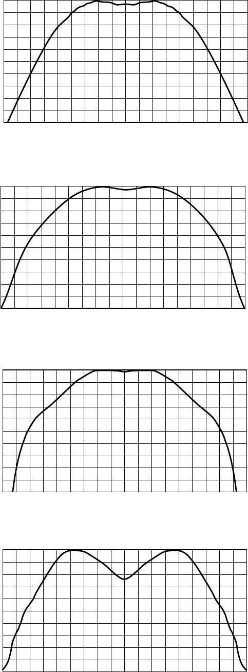
Figure 5. Relativ
e intensity vs. angle for HSMx
-C110.
Figure 6. Relativ
e intensity vs. angle for HSMx
-C120.
RELATIVE INTENSITY – %
100
0
ANGLE
80
60
20
40
-70
-50
-30
30
50
70
90
-90
-10
10
RELATIVE INTENSITY – %
100
0
ANGLE
80
60
20
40
-70
-50
-30
30
50
70
90
-90
-10
10
100
90
80
70
60
50
40
30
20
10
0
RELATIVE INTENSITY
-90
-80
-70
-60
-50
-40
-30
-20
-10
0
10
20
30
40
50
60
70
80
90
ANGLE
100
90
80
70
60
50
40
30
20
10
0
RELATIVE INTENSITY
-90
-80
-70
-60
-50
-40
-30
-20
-10
0
10
20
30
40
50
60
70
80
90
ANGLE
8
Figure 9. Relativ
e intensity vs. angle for HSMx
-C170, C190, C191, and C150.
Figure 7. Relativ
e intensity vs. angle for HSMx
-C177 and C197.
Figure 8. Relativ
e intensity vs. angle for HSMx
-C130.
Figure 10. Relativ
e intensity vs. angle for HSMx
-C265.
RELATIVE INTENSITY – %
100
0
ANGLE
80
60
50
70
20
10
30
40
90
-70
-50
-30
0
20
30
50
70
90
-90
-20
-80
-60
-40
-10
10
40
60
80
RELATIVE INTENSITY – %
100
0
ANGLE
80
60
50
70
20
10
30
40
90
-70
-50
-30
0
20
30
50
70
90
-90
-20
-80
-60
-40
-10
10
40
60
80
RELATIVE INTENSITY – %
100
0
ANGLE
80
60
50
70
20
10
30
40
90
-70
-50
-30
0
20
30
50
70
90
-90
-20
-80
-60
-40
-10
10
40
60
80
RELATIVE INTENSITY – %
100
0
ANGLE
80
60
50
70
20
10
30
40
90
-70
-50
-30
0
20
30
50
70
90
-90
-20
-80
-60
-40
-10
10
40
60
80
9
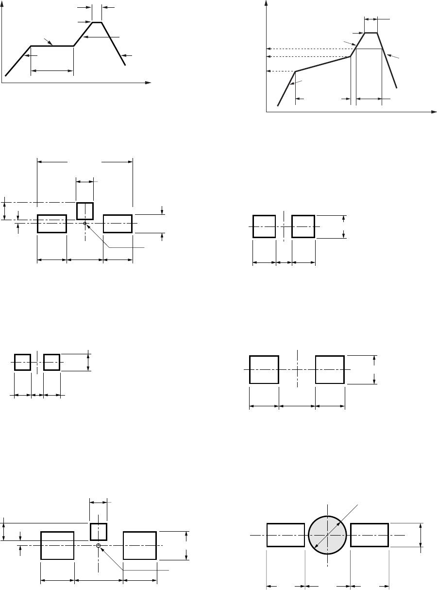
Figure 12. Recommended Pb-free reflow soldering profile.
Figure 13. Recommended soldering pattern f
or HSMx-C110.
Figure 14. Recommended soldering pattern f
or HSMx-C170/177.
5.0 (0.200)
1.0 (0.039)
1.5
(0.059)
1.5
(0.059)
2.0
(0.079)
0.9 (0.035)
0.2 (0.008)
0.9 (0.035)
CENTERING
BOARD
NOTE:
1. ALL DIMENSIONS IN MILLIMETERS (INCHES).
1.2 (0.047)
1.2
(0.047)
0.9
(0.035)
1.2
(0.047)
Figure 16. Recommended soldering pattern f
or HSMx-C150.
1.5 (0.059)
1.5
(0.059)
1.5
(0.059)
2.0
(0.079)
Figure 15.
Recommended soldering
pattern for
HSMx-
C130/190/191/197.
0.8 (0.031)
0.8
(0.031)
0.7
(0.028)
0.8
(0.031)
Figure 17. Recommended soldering pattern f
or HSMx-C120.
Figure 18. Recommended soldering pattern f
or HSMx-C265.
0.7 (0.028)
0.8
(0.031)
0.8
(0.031)
1.2
(0.047)
0.4 (0.016)
0.15 (0.006)
0.4 (0.016)
CENTERING
BOARD
1.25 (0.049)
1.4
(0.055)
2.3
(0.091)
1.4
(0.055)
2.2 (0.087) DIA. PCB HOLE
Figure 11. Recommended reflow soldering profile
.
230°C MAX.
10 SEC. MAX.
4°C/SEC.
MAX.
OVER 2 MIN.
TIME
TEMPERATURE
4°C/SEC. MAX.
140-160°C
3°C/SEC. MAX.
21
7
C
20
0
C
6
0
-
1
20
S
EC
.
6
C/
SE
C
.
MA
X.
3
C/
SE
C
.
MA
X.
3
C/
SE
C
.
MA
X.
15
0
C
25
5
-
2
60
C
60
S
EC
.
M
AX
.
10
S
EC
.
M
AX
.
TIME
TEMPERA
TURE
P1-P3
P4-P6
P7-P9
P10-P12
HSMQ-C120
Mfr. #:
Buy HSMQ-C120
Manufacturer:
Broadcom / Avago
Description:
Standard LEDs - SMD InGaN Green n Grn
Lifecycle:
New from this manufacturer.
Delivery:
DHL
FedEx
Ups
TNT
EMS
Payment:
T/T
Paypal
Visa
MoneyGram
Western
Union
Products related to this Datasheet
HSMR-C191
HSMQ-C170
HSMR-C265
HSMR-C150
HSMQ-C190
HSMQ-C120
HSMR-C110
HSMQ-C110
HSMQ-C191
HSMR-C197
HSMQ-C177
HSMR-C120
HSMR-C170
HSMR-C130
HSMQ-C150
HSMR-C190