EH301

©2015 Advanced Linear Devices, Inc., Vers. 2.2 www.aldinc.com 1 of 4
GENERAL DESCRIPTION
EH300/EH301 Series EPAD
®
Energy Harvesting
TM
Modules can
accept energy from many types of electrical energy sources and
store this energy to power conventional 3.3V and 5.0V electrical
circuits and systems. EH300/EH301 Series modules are com-
pletely self-powered and always in the active mode. They are
intended for low power intermittent duty cycle sampled data or
condition-based monitoring/ extreme lifespan applications. These
modules can accept instantaneous input voltages ranging from
0.0V to +/-500V AC or DC, and input currents from 200nA to 400mA
from energy harvesting sources that produce electrical energy in
either a steady or an intermittent and irregular manner with vary-
ing source impedances. EH300/EH301 Series modules condition
the stored energy to provide power at output voltage and current
levels that are within the limits of a particular electronic system
power supply specifications. For example, 1.8V and 3.6V is a useful
voltage range for many types of IC circuits, such as microproces-
sors.
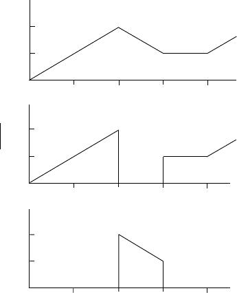
EH300/EH301 Series modules are designed to continuously and
actively operate to capture, accumulate, and conserve energy from
an external energy source. Each individual EH300/EH301 Series
module is set to operate between two supply voltage thresholds,
+V_low
DC and +V_high DC, corresponding to the minimum (V
L
)
and maximum (V
H
) supply voltage values for the intended appli-
cation. When an energy source starts to inject energy into the
inputs of an EH300/EH301 Series module in the form of electrical
charge impulses, these charge packets are collected, accumulated
and stored onto an internal storage capacitor bank. For most com-
mon energy harvesting applications, the electrical energy charge
packets arrives in the form of input voltage spikes that are uncon-
trolled and unpredictable. Often these cover a wide range of volt-
ages, currents and timing waveforms. EH300/EH301 Series mod-
ules are designed to accommodate such conditions with excep-
tional efficiency and effectiveness
. As an example, a EH300 mod-
ule can cycle within 4 minutes at an average input current of 10µA
and within 40 minutes at an average input current of just 1.0µA.
BENEFITS
Eliminates manual and elaborate
system trimming procedures
Remote controlled automated trimming
In-System Programming capability
No external components
No internal clocking noise source
APPLICATIONS
Sensor interface circuits
Transducer biasing circuits
Capacitive and charge integration circuits
Biochemical probe interface
Signal conditioning
Portable instruments
e
EPAD
TM
®
N
A
B
L
E
D
E
EH300/301 EPAD
®
ENERGY HARVESTING
TM
MODULES
EH300/EH300A/EH301/EH301A
A
DVANCED
L
INEAR
D
EVICES,
I
NC.
ORDERING INFORMATION
Part Number Description
EH300 4.6 mJ Module / 1.8V to 3.6V operation
EH300A 30 mJ Module / 1.8V to 3.6V operation
EH301 8.3 mJ Module / 3.1V to 5.2V operation
EH301A 55 mJ Module / 3.1V to 5.2V operation
EHJ1C 6 inch cable / J1connector (Input)
EHJ2C 6 inch cable / J2 connector (Output)
Note: EH300A and EH301A are high energy output versions
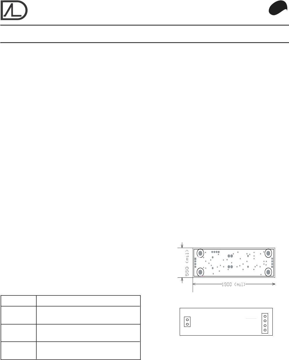
MECHANICAL SPECIFICATIONS
Outline Dimensions:
W x L x H : 0.55 in. x 2.00 in. x 0.70 in.
4 Mounting Holes: 0.085 in. diameter
Weight: 0.5 ounce (14 grams) nominal
J1
J2
Socket Adapter Cable:
J1: Hirose Socket, 2 Position P/N : DF13-2S
J2: Hirose Socket, 4 Position P/N : DF13-4S
+Input
-Input
Ground
VR (Ready)
VP (Output)
+V
4
3
2
1
2
1
Top View
EH300/EH300A/EH301/EH301A Advanced Linear Devices, Inc. 2 of 4
V
H
V
L
t
1
t
3
t
2
t
4
+
V
EH300/EH301 Waveforms
V
H
V
L
V
P
t
1
t
3
t
2
t
4
OUTPUT
V
H
V
L
t
1
t
3
t
2
t
4
V
R
READY
ENVIRONMENTAL SPECIFICATIONS
• Leadfree (ROHS) compliant
• Operating Temperature Range: 0 to 70° C
• Max. Average Operating Temperature : 50° C
• Storage Temperature: -40 to +85° C
• Humidity: To 90% (no condensation)
• Protection: Conformal and Epoxy coated
FUNCTIONAL DESCRIPTION
The EH300/EH301 Series module's voltage on the onboard
storage capacitor bank is +V, which is also the positive sup-
ply voltage switched to power the output power load. Ini-
tially, +V voltage on an EH300/EH301 Series module starts
at 0.0V. During the initial charge period, +V starts charging
from 0.0V. The module's internal circuit monitors and de-
tects this +V voltage. When +V reaches V
H
, the module
output (V
P
) is enabled and turned to the ON state and is
then able to supply power to a power load, such as a micro-
processor and/or a sensor circuit. The amount of useful en-
ergy available is a function of the capacity of the storage
capacitor bank. Meanwhile, an EH300/EH301 Series mod-
ule continues to accumulate any energy generated by ex-
ternal energy sources. If external energy input availability is
high, output V
P
remains in an ON state continuously, until
such time that external energy availability is lower than the
power demand required by the power load. As external en-
ergy input exceeds power loading, +V increases until inter-
nal voltage clamp circuits limit it to a maximum clamp volt-
age.
During normal operation, as power is drawn from an EH300/
EH301 Series module, +V decreases in voltage. When +V
reaches V
L
, output V
P
switches to an OFF state and stops
supplying any further power to the power load. With built-in
hysteresis circuits within the module, V
P
now remains in the
OFF state, even when the external energy source starts
charging the capacitor bank again by importing fresh new
impulses of electrical energy. Once V
H
level is reached again,
output V
P
is then turned to the ON state again. Hence +V
voltage cycles between V
H
to V
L
voltage levels and then to
the OFF state. When in the ON state, V
P
can supply up to
1A of current for a limited time period as determined by the
stored useful energy and the energy demand by the power
load. An optional input/ouput pin V
R
functions as V
P
on/off
control (external input through 1K) or as READY logical
control (output) signal preceeding output V
P
switching.
Input energy charging times t1 and t2 are limited by input
energy available minus energy loss by an EH300/EH301
Series module. The energy output time period t3 is deter-
mined by the rate of energy used by the power load as a
function of energy stored. Low input energy hold time t4 is
typically many orders of magnitude greater than the sum of
t1, t2 and t3.
INITIAL SETUP & CALIBRATION
EH300/EH301 Series modules are setup and calibrated
at the factory to standard specifications and settings.
No user setup is required. Optional user control signal
and connection to external capacitor or battery storage
banks are available at the output port. All EH300/EH301
Series modules are shipped ready to use.
EH300/EH300A/EH301/EH301A Advanced Linear Devices, Inc. 3 of 4
T
A
= 25
o
C,
V
IN
= 6.0V
unless otherwise specified
Max. instantaneous input voltage +/- 500V
Max. instantaneous input current 400mA
Max. input/output power 500 mW
Operating temperature range 0°C to +70°C
Min. input 0.0V@1nA
Internal voltage clamp 7.0V@10mA
Max. output current 1A
CAUTION: ESD Sensitive Device. Use static control procedures in ESD controlled environment.
ABSOLUTE MAXIMUM and MINIMUM RATINGS
OPERATING ELECTRICAL CHARACTERISTICS
T
A
= 25
o
C,
V
IN
= 4.0V
unless otherwise specified
EH300 EH300A
Parameter Symbol Min Typ Max Min Typ Max Unit Test Conditions
Output Low Level V
L
1.9 1.9 V
Output High Level V
H
3.5 3.5 V
Charging Input V
in
4.0/200 4.0/200 V@nA
Power Dissipation P
D
0.4 0.8 1 2 µW
Useful Energy Output E 4.6 30 mJ 1 cycle
Output On-time Rating t
*
I 68/25 75/150 msec@mA 1 cycle
V
P
Output Resistance R
V
P
0.15 0.15 V
P
= 3.5V
V
R
Output Sink Current I
Rsink
2.5 2.5 mA V
P
= 3.5V, V
R
= 3.5V
V
R
Output Source Current I
Rsource
-1.0 -1.0 mA V
P
= 3.5V, V
R
= 0.0V
Output Load R
load
3.5 3.5 I
out
= 1A
Output Current I
out
11AR
load
= 3.5
EH301 EH301A
Parameter Symbol Min Typ Max Min Typ Max Unit Test Conditions
Output Low Level V
L
3.1 3.1 V
Output High Level V
H
5.2 5.2 V
Charging Input V
in
6.0/300 6.0/300 V@nA
Power Dissipation P
D
0.9 1.8 1.5 3 µW
Useful Energy Output E 3.9 55 mJ 1 cycle
Output On-time Rating t
*
I 80/25 885/150 msec@mA 1 cycle
V
P
Output Resistance R
V
P
0.1 0.1 V
P
= 5.0V
V
R
Output Sink Current I
Rsink
5 5 mA V
P
= 5.0V, V
R
= 5.0V
V
R
Output Source Current I
Rsource
-2 -2 mA V
P
= 5.0V, V
R
= 0.0V
Output Load R
load
55 I
out
= 1A
Output Current I
out
11AR
load
= 5.0

EH301

Mfr. #:
Manufacturer:
Description:
MODULE ENERGY HARVESTER W/CONN
Lifecycle:
New from this manufacturer.
Delivery:
DHL FedEx Ups TNT EMS
Payment:
T/T Paypal Visa MoneyGram Western Union

Products related to this Datasheet