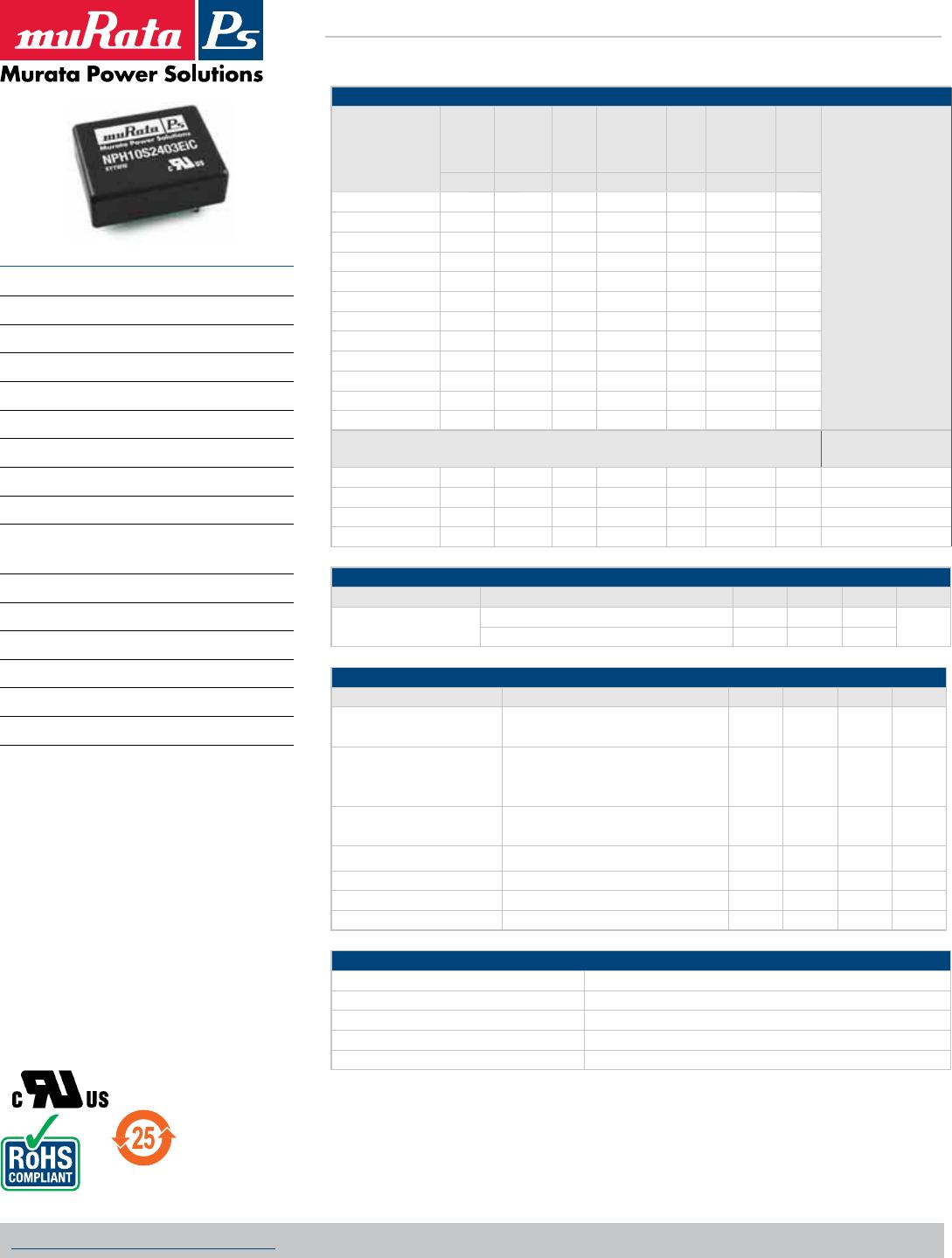
NPH10S2415IC

NPH10S Series
Isolated 10W Single Output DC/DC Converters
KDC_NPH10SC.J03 Page 1 of 8
www.murata-ps.com
www.murata-ps.com/suppor t
For full details go to
www.murata-ps.com/rohs
 
SELECTION GUIDE
Order Code
1
Nominal
Input
Voltage
Output
Voltage
Output
Current
Current
Limit
2
(Typ.)
Efficiency
Max. Load
Capaci-
tance
MTTF
3
V V A A % μF kHrs
NPH10S2403EiC 24 3.4 2.94 4.3 79 470 279
NPH10S2403iC 24 3.4 2.94 4.3 79 470 279
NPH10S2405EiC 24 5.1 1.96 3.1 83 470 275
NPH10S2405iC 24 5.1 1.96 3.1 83 470 275
NPH10S2412EiC 24 12.1 0.83 1.2 86 100 259
NPH10S2412iC 24 12.1 0.83 1.2 86 100 259
NPH10S2415EiC 24 15.1 0.67 1.1 86 47 243
NPH10S2415iC 24 15.1 0.67 1.1 86 47 243
NPH10S4803EiC 48 3.4 2.94 4.1 80 470 317
NPH10S4803iC 48 3.4 2.94 4.1 80 470 317
NPH10S4805EiC 48 5.1 1.96 2.8 83 470 312
NPH10S4805iC 48 5.1 1.96 2.8 83 470 312
Obsolete
Recommended
Alternative
NPH10S4812EiC 48 12.1 0.83 1.3 86 56 291 UEI15-120-Q48P-C
NPH10S4812iC 48 12.1 0.83 1.3 86 56 291 UEI15-120-Q48P-C
NPH10S4815EiC 48 15.1 0.67 1.0 87 22 272 UEI15-150-Q48P-C
NPH10S4815iC 48 15.1 0.67 1.0 87 22 272 UEI15-150-Q48P-C
INPUT CHARACTERISTICS
Parameter Conditions Min. Typ. Max. Units
Voltage range
Continuous operation, 24V input types 18 24 36
V
Continuous operation, 48V input types
4
36 48 75
OUTPUT CHARACTERISTICS
Parameter Conditions Min. Typ. Max. Units
Voltage set point error
50% load after 30 mins at nominal sup-
ply voltage
0.5 %
Overall voltage error
Case temperature -40ºC to 110ºC
Load 0% - 100%
Input specified range
1 2.5 %
Temperature coefficient of
output voltage (slope)
Over any 10ºC span within the specified
temperature range
50 250 ppmºC
Deviation of output voltage Specified over temperature MIN-MAX 0.5 1 %
Line regulation Operating voltage range, 50% load 0.05 0.1 %
Load Regulation 0% - 100% rated load
5
0.5 %
Ripple rms 70 mV
ABSOLUTE MAXIMUM RATINGS
Input voltage, 24V input types -0.5V to 40V
6
Input voltage, 48V input types -0.5V to 80V
6
Output voltage -0.3V to controlled output voltage (operating or non-operating)
Output trim control -1V to +30V
Synchronisation/shutdown control ±15V relative to input return
1. Parts ending with EiC have optional TRIM and SS pins fitted.
2. Current is quoted when output is 95% of regulated voltage.
3. Calculated using MIL-HDBK-217F with nominal input voltage at full load.
4. For applications requiring UL 1950 recognition, input voltage must not exceed 60VDC.
5. A minimum load of 10% of rating is recommended for typical applications.
6. Absolute maximum value for 30 seconds. Prolonged application may damage the product.
All specifications typical at T
A=25°C, nominal input voltage and rated output current unless otherwise specified.
FEATURES
RoHS compliant
High efficiency to 87%
Power density up to 1.5Wcm
3
UL1950 recognized
Industry standard pinout
Surge rating to 12W
Non latching current limit
1.5kV input to output isolation
Versatile control options
Continuous rating to 10W at 72ºC without
heatsink
Operation to zero load
Protected against load faults
Internal over temperature protection
Uses no electrolytic capacitors
Fixed frequency
No external components required
DESCRIPTION
The NPH10S series of DC/DC converters combines
ease of application with versatility. The pin pattern
is based on the popular industry standard, but two
additional pins may optionally be fitted to provide
a variety of features not commonly found on units
of this type. High efficiency enables full rating to
be achieved in a small package without heat-
sinking. Thermally protected against sustained
overload. The copper case achieves efficient heat
transfer and screening. The product range has
been recognised by Underwriters Laboratory (UL)
to UL 1950 for operational insulation, file number
E151252 applies.
NPH10S Series
Isolated 10W Single Output DC/DC Converters
KDC_NPH10SC.J03 Page 2 of 8
www.murata-ps.com/suppor t
CONTROL CHARACTERISTICS
Parameter Conditions Min. Typ. Max. Units
Voltage trimming range
1
At rated load, trim control at either output ±10 %
Remote switch input (voltage relative to
input negative)
1
For shutdown -15 0 1.5
V
Operating, open circuit voltage 9 10 11
Start delay
Time from application of valid input voltage to output being in specifi-
cation
25 ms
Synchronisation
1
Specified drive signal 320 440 kHz
Switching frequency 330 350 395 kHz
ISOLATION CHARACTERISTICS
Parameter Conditions Min. Typ. Max. Units
Isolation test voltage Flash tested for 1 second 1500 VDC
Resistance VISO = 500VDC 1
Capacitance
3.3V and 5V output 50
pF
12V and 15V output 90
TEMPERATURE CHARACTERISTICS
Parameter Conditions Min. Typ. Max. Units
Case temperature Full load -40 110
ºC
Storage Absolute Max. internal temperature -40 125
Relative humidity Non condensing 85ºC 85 %
Thermal protection Operates at case temperature 110 ºC
THERMAL CHARACTERISTICS
Max. power rating with case temperature maintained by external means (e.g. forced air cooling).
Part Number
Case Temperature
Units
100ºC 105ºC 110ºC
NPH20S2403XXX 10 7.0 2.3
W
NPH10S2405XXX 10 8.2 3.0
NPH10S2412XXX 10 9.5 4.0
NPH10S2415XXX 12 9.5 4.0
NPH10S4803XXX 10 7.0 1.0
W
NPH10S4805XXX 10 4.7 1.0
NPH10S4812XXX 12 8.0 0
NPH10S4815XXX 12 7.5 0
THERMAL PERFORMANCE
24V Input 48V Input
1. Optional - where fitted.
"NCJFOU5FNQFSBUVSF
¡$
"NCJFOU5FNQFSBUVSF
¡$
  
 
     


 
0VUQVU1PXFS8
0VUQVU1PXFS8








NPH10S Series
Isolated 10W Single Output DC/DC Converters
KDC_NPH10SC.J03 Page 3 of 8
www.murata-ps.com/suppor t
APPLICATION NOTES
OUTPUT VOLTAGE ADJUSTMENT
V
NOM 3.4 5.1 12.1 15.1
S 22.2973 20.59761 28.79096 39.95902
T 10.1351 9.36255 15.42373 20.77869
R 17.9994 24.49487 94.9661 147.7314
L -1.6241 -2.48374 -5.942857 -7.990244
TRIM UP TRIM DOWN
When the output voltage is trimmed up, output current must be derated so that the maximum output power 10W is not exceeded.
Example to decrease output voltage of NPH10S4805EiC by 0.1V:
SET VOLTAGE
The output voltage of all units is set to 100mV above nominal, to offset resistive losses and thus assist with worst case error calculations. For the EiC versions, this
allowance can be altered with a single fixed resistor, connected from the trimming pin to one of the output pins.
SHUTDOWN
FREQUENCY CONTROL
When the shutdown pin (SS) is shorted to the negative input, the converter will
stop. Its current consumption will then be less than 1mA at nominal supply volt-
age. The voltage must be less than 1.5V to ensure that the unit stops, and must
be able to sink at least 1mA.
The unit will restart if the control pin is left open circuit or raised to a value
close to its normal open circuit voltage. This is typically 10V. Note however, that
the unit will not meet specification while a significant current drain from this pin
remains.
If the shutdown pin is to be connected to a long wire, it is recommended that a
capacitor decouples the pin to the supply common in order to avoid the risk of
injecting noise into the converter circuit. A series resistor may also be helpful.
Values of 10nF and 1kΩ may be used.
Many NPH series converters may be switched together simply by linking the
primary control pins. The primary common pins must also be linked.
If the primary side dc control voltage is pulled away from its open circuit
voltage, the converter frequency will be changed, approximately in proportion
to the voltage. With +8.5VDC voltage to SS pin, the typical switching frequency
will be 300kHz. If this is raised to 15VDC, the switching frequency will typically
be 510kHz. The frequency may thus be moved away from a sensitive value or
into a safe area. Deviation of at least –10% to 30% is achievable, though the
efficiency will decline with significant changes. Also note that if the frequency
is lowered, the switching frequency component of output ripple will increase.
Since the design uses no large electrolytic capacitors, any use of a lower
frequency must allow for the effects of increased ripple. Additional external
filtering may be required.
+VIN
+VOUT
-VOUT
TRIM
R
UP
NPH10S
The trim resistor equations are:
Rup = (R/Vup) - S kΩ
Rdown = (L x
T
) - T - S kΩ
V
down
+VIN
+VOUT
TRIM
RDOWN
NPH10S
-VOUT
RDOWN =
-2.48374 x 9.36255 - 9.36255 - 20.59761 = 203.18kΩ
(
)
-0.1

NPH10S2415IC

Mfr. #:
Manufacturer:
Description:
Isolated DC/DC Converters 10W 24V IN 15.1 OUT Single Output
Lifecycle:
New from this manufacturer.
Delivery:
DHL FedEx Ups TNT EMS
Payment:
T/T Paypal Visa MoneyGram Western Union