Typical Operating Characteristics (continued)
(V
S
= +48V, GND = 0V, and T
A
= +25°C, unless otherwise noted. See Figure 2 for test circuits.)
MAX5902/MAX5903
+72V, SOT23/TDFN, Simple Swapper Hot-Swap
Controllers
4 _______________________________________________________________________________________
5
7
11
9
13
15
03015 45 60 75
GATE DRIVE VOLTAGE
vs. INPUT VOLTAGE
MAX5902 toc04
INPUT VOLTAGE (V)
GATE DRIVE (V)
75
125
100
175
150
200
225
-40 10-15 356085
RETRY TIMEOUT
vs. TEMPERATURE
MAX5902 toc05
TEMPERATURE (
°
C)
TIMEOUT PERIOD (ms)
t = 20ms/div
TURN-ON WAVEFORMS
R
L
= 60, C
L
= 100µF
A : V
OUT
, 50V/div
B : I
IN
, 1A/div
C : V
GATE
, 50V/div
D : V
IN
, 50V/div
A
B
D
C
MAX5902 toc06
0
0
0
0
t = 2ms/div
TURN-ON WAVEFORMS
R
L
= OPEN, C
L
= 100µF
A : V
OUT
, 50V/div
B : I
IN
, 1A/div
C : V
GATE
, 20V/div
A
B
C
MAX5902 toc07
0
0
0
t = 1µs/div
CIRCUIT-BREAKER EVENT
V
OVERDRIVE
= 20mV, C
GATE
= 1000pF
A
B
C
MAX5902 toc10
0
0
0
A : V
DS
, 0.5V/div
B : V
GS
, 10V/div
C : V
PGOOD
TO V
S
, 50V/div
t = 2ms/div
TURN-ON WAVEFORMS
R
L
= 60, C
L
= 10µF
A : V
OUT
, 50V/div
B : I
IN
, 0.5A/div
C : V
GATE
, 20V/div
A
B
C
MAX5902 toc08
0
0
0
t = 1µs/div
CIRCUIT-BREAKER EVENT
V
OVERDRIVE
= 200mV, C
GATE
= 1000pF
A
B
C
MAX5902 toc11
0
0
0
A : V
DS
, 0.5V/div
B : V
GS
, 10V/div
C : V
PGOOD
TO V
S
, 50V/div
t = 2ms/div
TURN-ON WAVEFORMS
R
L
= 60, C
L
= 100µF
A : V
OUT
, 50V/div
B : I
IN
, 1A/div
C : V
GATE
, 20V/div
A
B
C
MAX5902 toc09
0
0
0
MAX5902/MAX5903
+72V, SOT23/TDFN, Simple Swapper Hot-Swap
Controllers
_______________________________________________________________________________________ 5
Detailed Description
The MAX5902/MAX5903 are integrated hot-swap con-
troller ICs contained in 6-pin SOT23 and TDFN pack-
ages. They allow a board to be safely hot-plugged into
a live backplane without causing a glitch on the power-
supply rail. They are well suited for +48V power sys-
tems allowing cost-effective, simple, and compact
design. The MAX5902/MAX5903 operate from +9V to
+72V to cover a wide range of end equipment hot-swap
needs. They require only an external p-channel power
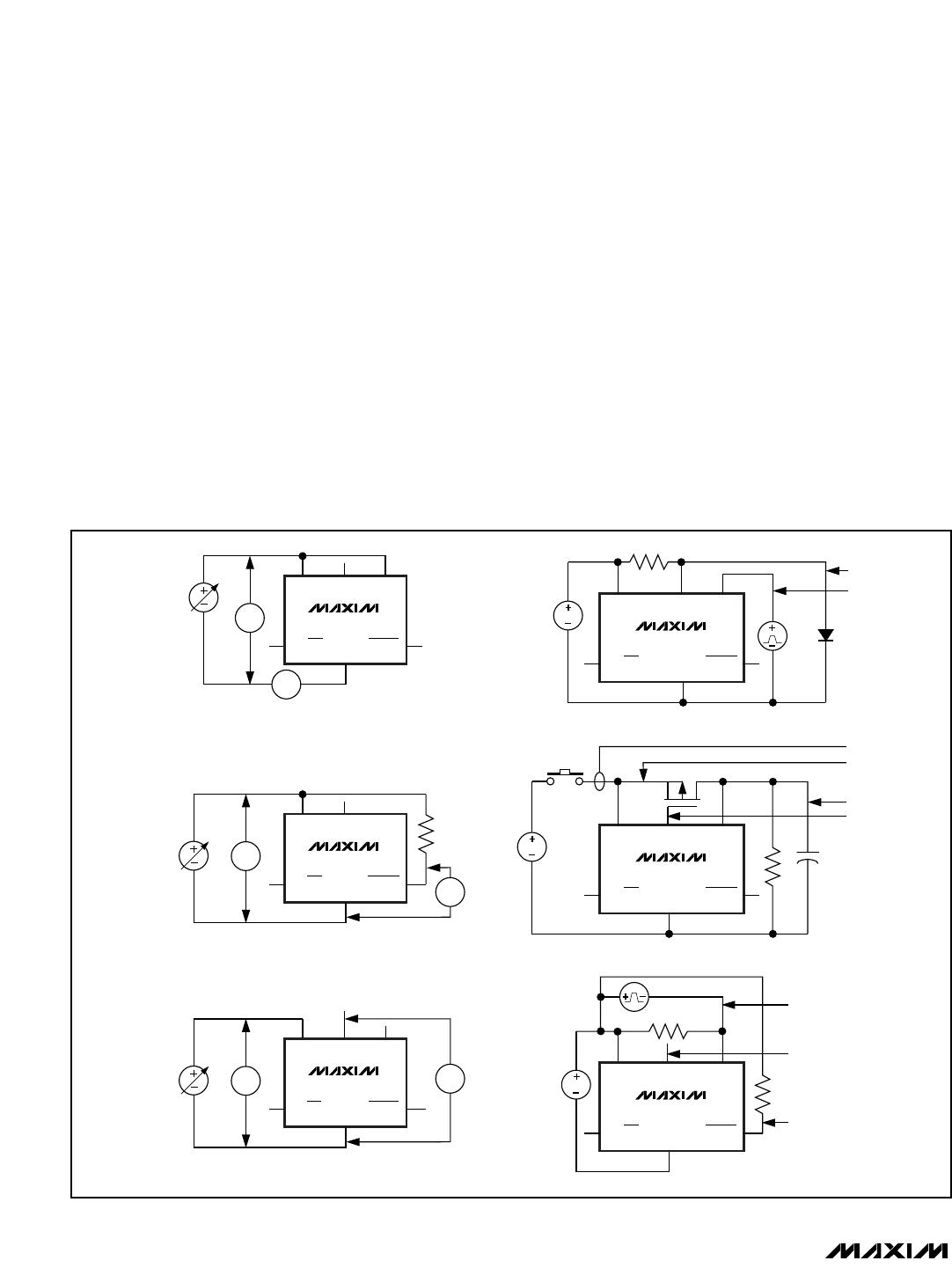
MOSFET to provide hot-swap control. Figure 1 shows a
functional block diagram of the MAX5902/MAX5903.
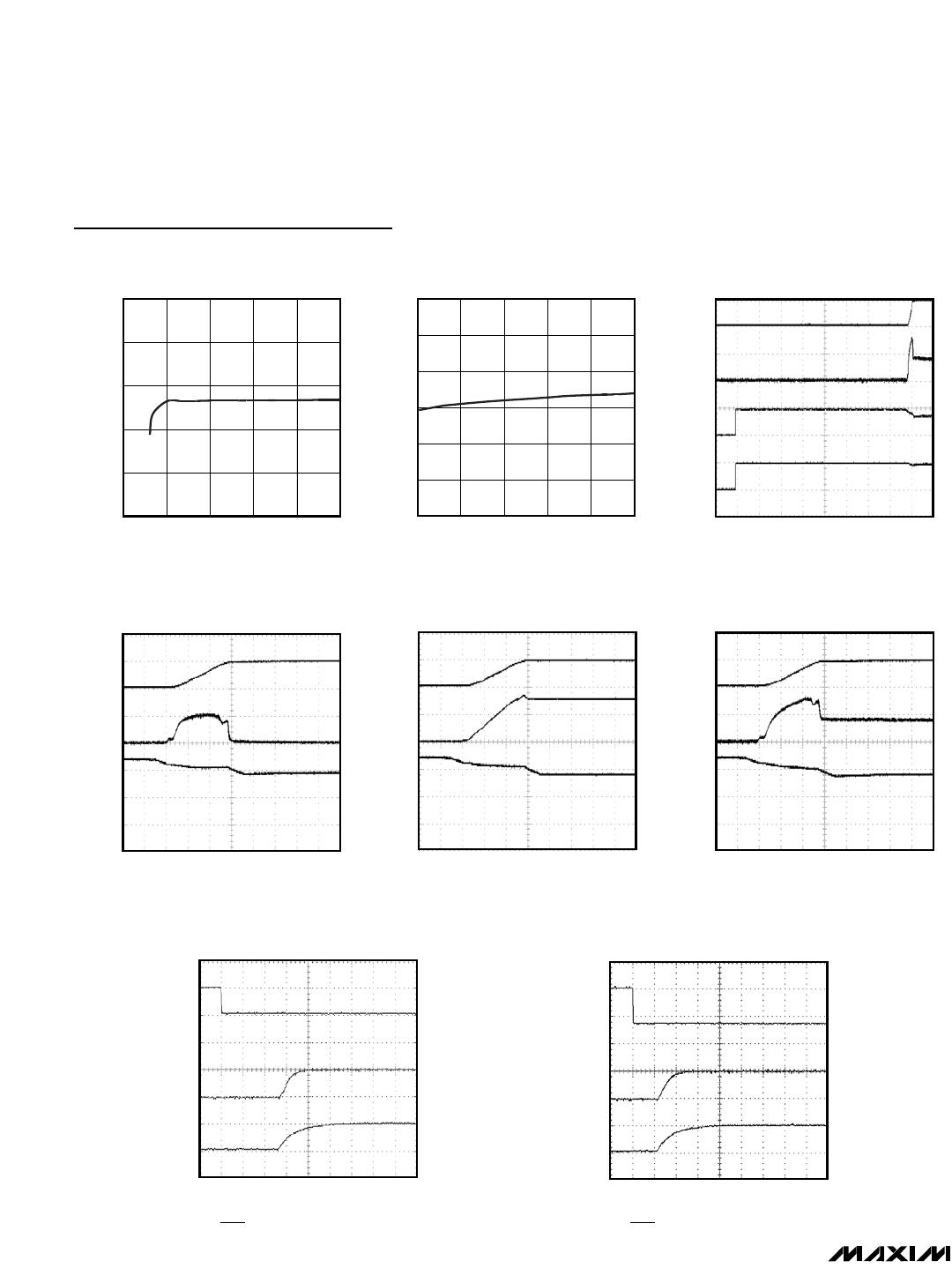
The MAX5902/MAX5903 controls an external p-channel
power MOSFET placed in the positive power-supply
pathway. When power is first applied, the MAX5902/
MAX5903 keep the MOSFET turned off. The
MAX5902/MAX5903 hold the MOSFET off indefinitely if
ON/OFF is held low, if the supply voltage is below the
undervoltage lockout level, or if the die temperature
exceeds +125°C. If none of these conditions exist for
150ms (typ), the MAX5902/MAX5903 begin to gradually
turn on the MOSFET. During this turn-on phase, the
MAX5902/MAX5903 slowly enhance the MOSFET,
allowing the voltage on the load, i.e. the drain of the
MOSFET, to rise at a rate of 9V/ms (typ). The inrush cur-
rent to the load is thus limited to a level proportional to
the load capacitance, and the constant slew rate. After
the MOSFET is fully enhanced, and the load voltage is
settled to its final value, the MAX5902A/ MAX5903A and
MAX5902L/MAX5903L monitor the voltage drop across
the MOSFET. If the voltage drop exceeds the circuit-
breaker threshold the MAX5902A/MAX5903A and
V
S
ON/OFF
GND
GND
GND
3V
MAX5902
MAX5903
828k
*900k
34.5k
1k
GATE
DRAIN
CONTROL
LOGIC
PGOOD
(PGOOD)
( ) ARE FOR THE MAX5903 ONLY
* RELATIVE TOLERANCE ±1%, ABSOLUTE TOLERANCE ±50% (TYP)
*650k
*
*
Figure 1. Functional Block Diagram
Pin Description
PIN
MAX5902
MAX5903
NAME FUNCTION
11V
S
Positive Supply Voltage Input and External p-Channel MOSFET Source Connection
2 2 DRAIN
Drain Sense Input for External p-Channel MOSFET. Connect DRAIN as close as
possible to the MOSFET’s drain and use wide circuit traces to assure good thermal
coupling between the MAX5902/MAX5903 and the MOSFET. See Layout Guidelines
Section.
3 3 GATE Gate Drive Output for External p-Channel MOSFET
4 4 GND Ground Connection
5—PGOOD
Power-Good Output. PGOOD is an n-channel, open-drain, active-low output,
referenced to GND.
5 PGOOD
Power-Good Output. PGOOD is an n-channel, open-drain, active-high output,
referenced to GND.
6 6 ON/OFF
ON/OFF Control Input. ON/OFF is referenced to GND. Drive ON/OFF above 1.38V or
leave unconnected to enable the device. Drive ON/OFF below 1V to disable the device.
ON/OFF is also used to adjust the UVLO threshold. Internally clamped to nominally 3V
through a 1k resistor (See Figure 1). (See the Undervoltage Lockout section in the
Applications Information.)
EP Exposed Pad (TDFN only). Connect to GND.
MAX5902/MAX5903
+72V, SOT23/TDFN, Simple Swapper Hot-Swap
Controllers
6 _______________________________________________________________________________________
MAX5902L/MAX5903L turn off the MOSFET, discon-
necting the load immediately. If no circuit-breaker fault
exists, the MAX5902/MAX5903 assert the power-good
output. Then, if any of four conditions exist, the power-
good output deasserts and the MAX5902/MAX5903
turn off the MOSFET. The four conditions are: the volt-
age across the MOSFET exceeds the circuit-breaker
threshold; the supply voltage falls below the undervolt-
age lockout level; the die temperature exceeds
+125°C; or ON/OFF is forced low. After a circuit-break-
er fault, the MAX5902L/MAX5903L keep the MOSFET
off until the power is cycled, or the part is reset by tog-
gling ON/OFF low for 10ms (typ). After a circuit-breaker
fault, the MAX5902A/MAX5903A automatically restarts
in 150ms (typ). All versions automatically restart after a
thermal fault, or an undervoltage shutdown, if the fault
condition goes away for at least 150ms (typ).
ON/OFF offers external control of the MAX5902/
MAX5903, facilitating power-supply sequencing, and
may also be used to change the undervoltage lockout
(UVL) level. UVLO keeps the external MOSFET
switched off as long as the input voltage is below the
desired level.
A power-good output, PGOOD (MAX5902) or PGOOD
(MAX5903), asserts when the external MOSFET is fully
enhanced and the source-drain voltage is below the
circuit-breaker threshold. PGOOD and PGOOD are
open-drain outputs referenced to GND, and can with-
stand up to +72V.
GND
GATE DRAINV
S
50k
50
50k
50k
MAX5902
ON/OFF
PGOOD
V
I
V
IN
GND
GATE DRAINV
S
MAX5902
ON/OFF
PGOOD
V
V
V
IN
GND
GATE DRAINV
S
MAX5902
ON/OFF
PGOOD
V
V
V
IN
0 TO 0.5V
GND
GATE DRAINV
S
MAX5902A
ON/OFF
PGOOD
SCOPE
SCOPE
48V
C
L
R
L
GND
GATE DRAIN
IRFR5410
V
S
MAX5902
ON/OFF
PGOOD
SCOPE
SCOPE
SCOPE
SCOPE
48V
GND
GATE DRAINV
S
MAX5902
ON/OFF
PGOOD
SCOPE
SCOPE
SCOPE
48V
(a) SUPPLY CURRENT (d) RETRY TIMEOUT
(d) STARTUP WAVEFORMS
(d) CIRCUIT-BREAKER EVENT
(b) V
UVLO
(b) GATE DRIVE VOLTAGE
Figure 2. Test Circuits

MAX5903NNEUT+T

Mfr. #:
Manufacturer:
Maxim Integrated
Description:
Hot Swap Voltage Controllers 72V Hot-Swap Controller
Lifecycle:
New from this manufacturer.
Delivery:
DHL FedEx Ups TNT EMS
Payment:
T/T Paypal Visa MoneyGram Western Union