Si3453
Rev. 1.3 7
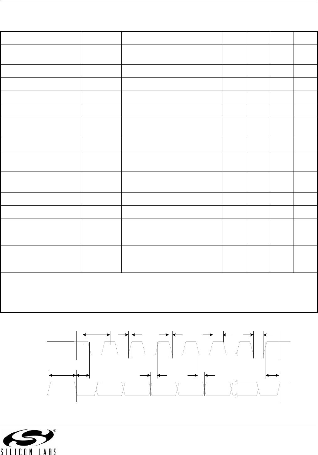
Table 6. VOUT Drive and Power-on Specifications
Description Symbol Test Conditions Min Typ Max Unit
Max Output Resistance
(Port On)
R
ON
I
Port
≤ 720 mA — 0.3 0.6 Ω
Current Limit I
LIM
1x mode, V
port
=V
EE
+ 1 V 400 425 450 mA
Change in Current Limit I
LIM
1x mode, V
port
=V
EE
+ 1V to –30V
1
–2 — 2 %
Current Limit I
LIM
2x mode, V
port
=V
EE
+ 1 V 800 860 920 mA
Change in Current Limit I
LIM
2x mode, V
port
=V
EE
+ 1V to –40V
2
–2 — 2 %
Current Limit I
LIM
1x mode or 2x mode, V
port
=–10V 60 — — mA
Overload Current
Threshold
I
CUT
Class 0
Class 1 (class policing enabled)
3
Class 2 (class policing enabled)
3
Class 3
Class 4
4
350
91
160
350
600
—
—
—
—
—
—
—
—
—
—
mA
Over Current Time
Limit
5
T
OVLD
Load current ≥ I
CUT
or I
LIM
50 — 75 ms
VOUTn Turn-on Slew T
RISE
10% to 90% 15 70 — µs
Power Turn On Timing T
PON
Time from end of valid detect to
power on
——400ms
VOUTn Leakage Cur-
rent
I
OUT_LEAK
Port in shutdown — — 10 µA
Notes:
1. T
J
>25 °C, –35 V over the full temperature range.
2. 1x mode current limit is enforced during the 60 ms T
START
time.
3. In auto mode, class policing is automatically enabled. In manual mode, I
CUT
must be programmed manually.
See "5.4. Port Configuration (Registers 0x0A–0x11)" on page 18 for more information.
4. 600 mA is consistent with the IEEE 802.3at draft standard. I
CUT
is user-programmable in 3.2 mA increments to over
800 mA for non-standard applications.
5. For 2x mode and extreme overload or short-circuit events, T
OVLD
will dynamically decrease to prevent excessive FET
heating. This is consistent with the 802.3at draft.
Table 7. DC Disconnect Specifications
Description Symbol Test Conditions Min Typ Max Unit
Load Current to Prevent
Disconnect
I
ON
10 — — mA
Load Current to
Guarantee Disconnect
I
OFF
dc disconnect — — 5 mA
Disconnect Delay
T
DCDV_DLY
Time from I
OFF
load current to port
turn off
300 — 400 ms