IMC-1210
www.vishay.com
Vishay Dale
Revision: 02-Jun-15
1
Document Number: 34043
For technical questions, contact: magnetics@vishay.com
THIS DOCUMENT IS SUBJECT TO CHANGE WITHOUT NOTICE. THE PRODUCTS DESCRIBED HEREIN AND THIS DOCUMENT
ARE SUBJECT TO SPECIFIC DISCLAIMERS, SET FORTH AT www.vishay.com/doc?91000
Wirewound, Surface Mount Molded Inductors
Note
(1)
Rated DC current based on the maximum temperature rise, not
to exceed 40 °C at +85 °C ambient
FEATURES
• Printed marking
• Molded construction provides superior strength
and moisture resistance
• Compatible with vapor phase and infrared reflow
soldering
• Tape and reel packaging for automatic handling,
2000/reel, EIA-481
• Material categorization: for definitions of compliance
please see
www.vishay.com/doc?99912
ELECTRICAL SPECIFICATIONS
Inductance range: 0.01 μH to 220 μH
Special tolerances available upon request
Operating temperature: -55 °C to +125 °C
Coilform material: Non-magnetic from 0.01 μH to 0.10 μH
Powdered iron from 0.12 μH to 100 μH
Ferrite from 120 μH to 220 μH
TEST EQUIPMENT
• HP4342A Q meter with Vishay Dale test fixture or equivalent
• HP4191A RF impedance analyzer (for SRF measurements)
• Wheatstone brigde
STANDARD ELECTRICAL SPECIFICATIONS
IND.
(μH)
TOL.
TEST FREQ.
(MHz)
Q
MIN.
SRF
MIN.
(MHz)
DCR
MAX.
()
RATED DC
CURRENT
(mA)
(1)
L & Q
0.010 20 % 50 30 1000 0.13 734
0.012 20 % 50 30 1000 0.14 707
0.015 20 % 50 30 1000 0.16 661
0.018 20 % 50 30 1000 0.18 624
0.022 20 % 50 30 1000 0.20 592
0.027 20 % 50 30 1000 0.22 564
0.033 20 % 50 30 1000 0.24 540
0.039 20 % 50 30 1000 0.27 530
0.047 20 % 50 30 1000 0.30 483
0.056 20 % 50 30 1000 0.33 470
0.068 20 % 50 30 1000 0.36 450
0.082 20 % 50 30 900 0.40 450
0.10 20 % 50 30 700 0.44 450
0.12 20 % 25.2 30 500 0.22 584
0.15 20 % 25.2 30 450 0.25 548
0.18 20 % 25.2 30 400 0.28 518
0.22 20 % 25.2 30 350 0.32 484
0.27 20 % 25.2 30 320 0.36 456
0.33 20 % 25.2 30 300 0.40 453
0.39 20 % 25.2 30 250 0.45 450
0.47 20 % 25.2 30 220 0.50 450
0.56 20 % 25.2 30 180 0.55 450
0.68 20 % 25.2 30 160 0.60 450
0.82 20 % 25.2 30 140 0.67 450
1.0 10 % 7.96 30 120 0.70 400
1.2 10 % 7.96 30 100 0.75 390
1.5 10 % 7.96 30 85 0.85 370
1.8 10 % 7.96 30 80 0.90 350
2.2 10 % 7.96 30 75 1.0 320
2.7 10 % 7.96 30 70 1.1 290
3.3 10 % 7.96 30 60 1.2 260
3.9 10 % 7.96 30 55 1.3 250
4.7 10 % 7.96 30 50 1.5 224
5.6 10 % 7.96 30 45 1.6 217
6.8 10 % 7.96 30 40 1.8 204
8.2 10 % 7.96 30 38 2.0 194
10 10 % 2.52 30 33 2.1 189
12 10 % 2.52 30 30 2.5 173
15 10 % 2.52 30 21 2.8 164
18 10 % 2.52 30 20 3.3 151
22 10 % 2.52 30 19 3.7 145
27 10 % 2.52 30 18 5.0 122
33 10 % 2.52 30 16 6.0 112
39 10 % 2.52 30 15 7.0 104
47 10 % 2.52 30 14 9.0 91
56 10 % 2.52 30 12 10.0 87
68 10 % 2.52 30 11 11.0 83
82 10 % 2.52 30 10 12.0 79
100 10 % 0.796 20 9 14.0 73
120 10 % 0.796 15 8 11.0 70
150 10 % 0.796 15 6.5 15.0 65
180 10 % 0.796 15 6 17.0 60
220 10 % 0.796 15 6 21.0 50
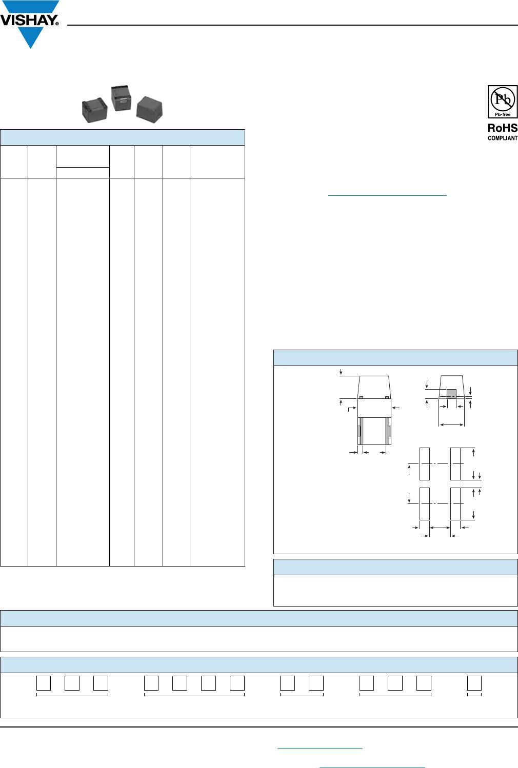
DIMENSIONS in inches [millimeters]
PART MARKING
- Vishay Dale
- Inductance value
- Date code
Guidelines for
Parallel Component
Printed Circuit
Mounting Pads on
IMC-1210-100
Chip Inductors
0.006
[0.152]
Ref.
Typ.
0.040
[1.02]
0.098 ± 0.008
[2.49 ± 0.203]
0.030
[0.762]
Typ.
0.126 ± 0.008
[3.20 ± 0.203]
0.028 ± 0.004
[0.711 ± 0.102]
Typ.
0.073
[1.85]
Ref.
0.087 ± 0.008
[2.21 ± 0.203]
0.118
[3.0]
0.118
[3.0]
0.039
[1.0]
0.039
[1.0]
0.070
[1.8]
0.138
[3.5]
0.020
(1)
[0.5]
Note
(1)
Recommended spacing between components
DESCRIPTION
IMC-1210
10 μH
± 10 % ER e3
MODEL INDUCTANCE VALUE INDUCTANCE TOLERANCE PACKAGE CODE JEDEC
®
LEAD (Pb)-FREE STANDARD
GLOBAL PART NUMBER
I M C 1 2 1 0 E R 1 0 0 K
PRODUCT
FAMILY
SIZE PACKAGE
CODE
INDUCTANCE
VALUE
TOL.