79552456

Products and specifications subject to change without notice.
Order/Technical Support – Tel: (800) 677-5311 / FAX: (800) 677-3865 / www.crouzet-usa.com
3/111
3
Limit Switches – Technical Guide
Rules and regulations
Electrical characteristics
Environmental conditions
Construction
Our detectors are designed to conform to international IEC
recommendations and/or European standards (EN).
Proof that a detector conforms to these standards or recommendations
takes the form of a conformity declaration made by the manufacturer
(drafted as indicated in guidance document ISO/IEC 22 - EN 450-14).
Characteristics in line with the general requirements of standards NFC
63140, IEC 947.5.1 and EN 60947.5.1.
- Leakage paths and air gaps : IEC 664.1 - NFC 20-040.
Our position detectors which comply with IEC 947.5.1 can be fitted to
machine-tools and industrial machines complying with NFC 79130, IEC
204.1, EN60204 or VDE 113.
Temperature limits
When they are used in the temperature range quoted, the mechanical and
electrical characteristics of our position detectors will remain substantially
unchanged. If you intend to use them outside this range, please consult us.
Protective treatment
The treatment given to our position detectors is suitable in the vast
majority of applications.
Parts made of steel are zinc-coated or painted according to their
mechanical function. Further information is available on request.
This treatment allows our detectors to be used under the following
temperature and humidity conditions :
T °C 20 40 50
Relative humidity % 95 80 50
This treatment may thus be suitable for applications in tropical or equatorial
climates where the equipment concerned is in an interior location sheltered
from direct exposure to atmospheric conditions.
Other types of reinforced protection are possible for resistance to very severe
environments.
Please enquire.
Mounting requirements
Electric shock protection.
The user should observe the mounting instructions relating to the mode of
protection against electric shocks defined in the IEC 536.1, EN 60204.1 -
NFC 20030 standards :
Class I : earth circuit link. Protection via differential circuit-breaker.
Class II : double insulation.
Class III : very low safety voltage.
Screw tightening torque :
1 : Actuator tightening 1.2 to 1.5 Nm
Plastic Metal
body body
2 : Head fixing screw 0.7 to 0.8 Nm 0.8 to 1 Nm
3 : Body fixing screw 0.7 to 0.8 Nm 0.8 to 1 Nm
4 : Fixing screw 2 to 2.5 Nm
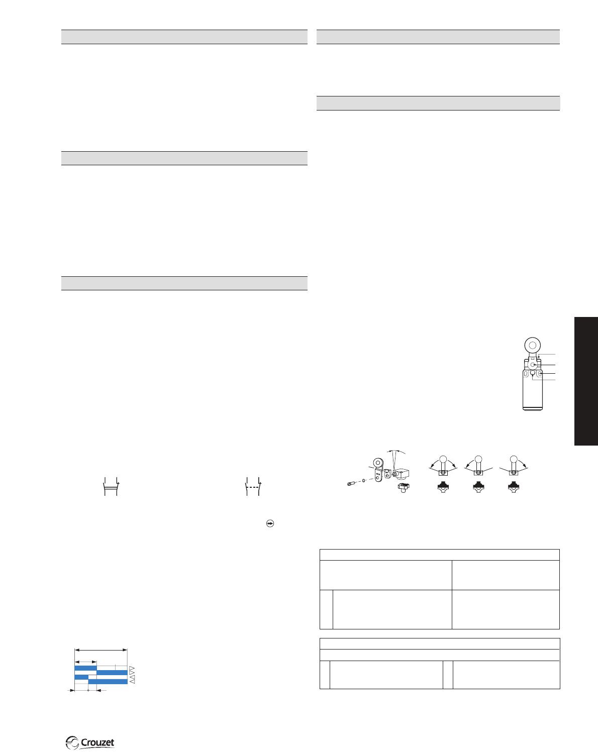
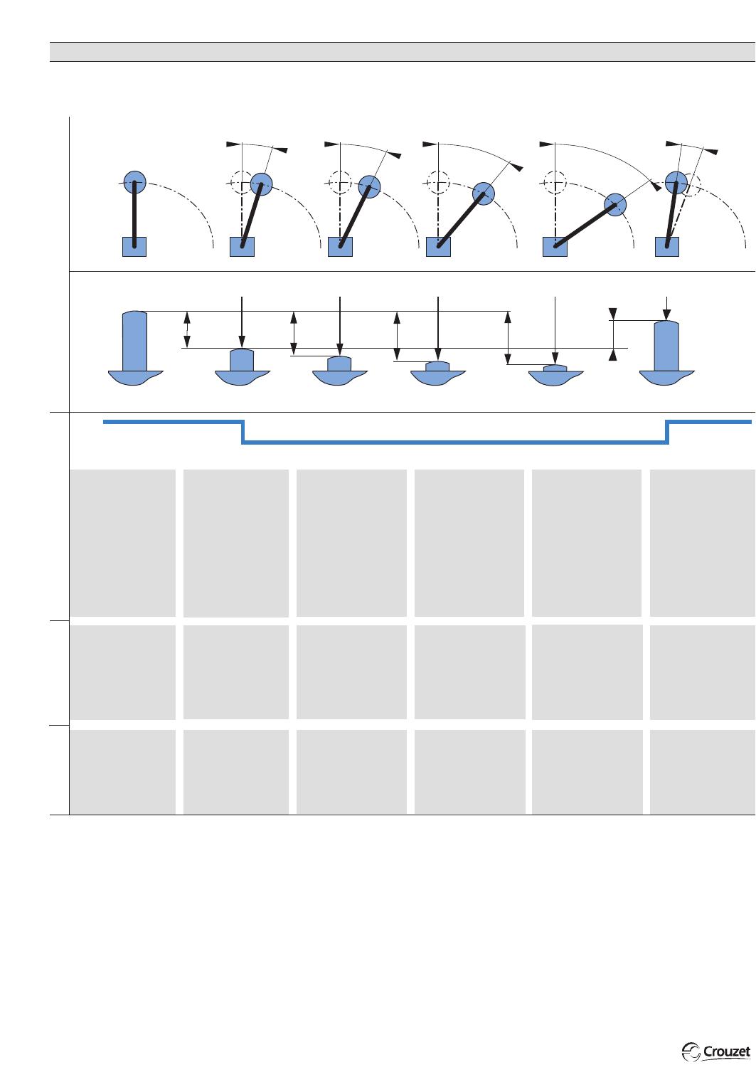
Adjustment of rotary heads with momentary action to right and left :
For series 83 850, 83 851, 83 861, 83 854, 83 855, 83 863
Degree of protection
Under the IEC 529 or NFC 20010 classification scheme, standards employ
an IP code to define the degree or class of protection which a position
detector provides against access to live components and against the entry
of solid foreign bodies and the entry of water.
Protection equipment provides
against the entry of solid
foreign bodies
0 (not protected)
4 diameter ≥1 mm
5 protected against dust
6 sealed against dust
0 (not protected)
4 splashed water
5 hosed water
6 high-pressure hosed water
7 temporary immersion
8 prolonged immersion
(not protected)
1 mm Ø wire
1 mm Ø wire
1 mm Ø wire
Protection for persons against
access to dangerous parts
Protection equipment provides against the entry of water
1
st
numeral
2
nd
numeral
Assigned working current (Ie):
- the current level adopted as a basis for the operating conditions quoted
for a detector, and for the life tests on it.
Thermal rating (Ith):
- the current the microswitch will withstand when not being operated
electrically, for a temperature rise of not more than 60 °C.
Assigned insulation voltage (Ui):
- the voltage adopted as a reference for the dielectric tests and leakage
paths. It must be equal to or greater than the assigned working voltage.
Categories of use (IEC 947.5.1):
- AC 15 for operating AC solenoids and electromagnets
- DC 13 for operating DC solenoids and electromagnets
Contact element designation
(IEC 947.5.1):
- a letter and number which define the use category and the assigned
working voltage and current
For example, A 300 means : in category AC 15, a maximum working
voltage of 300 V and 6 A at 120 V or 3 A at 240 V.
Contact block electrical wiring diagram
Form Za Form Zb
Both contacts have the The 2 contacts are
same polarity electrically isolated
Positive break contact operation (IEC 947-5-1, chapter 3)
For contacts used in safety applications, limit switches, emergency stop
devices, assurance that opening has occurred is essential (see IEC 204,
EN60204). After each attempt, contact opening is checked by an impulse
voltage test (2500 V).
What is meant by a "position detector" is any device which needs to be
operated by a member which exerts a physical force, in view of :
- either the form which its operating device takes
- or the considerable force needed to operate it
The distinguishing features of position detectors are :
- their high electrical performance capability
- their excellent resistance to accidental impact
- good protection against splashed or dripping water
- a wide range of operating devices to allow the detectors to be
adapted to a vast variety of mechanisms
EC Directives
Our detectors conform to the EC Low Voltage Technical Directive
73/23/EEC and can be used in accordance with the specifications of the
Machinery Directive 89/392/EEC.
Introduction
2
1
4
3
10° (x 360°)
Contact element :
- Snap action contact
This is characterized by tripping points and release points which cannot
be confused. The speed at which the control devices moves is
independent from the speed of the control device. This feature makes it
possible to obtain satisfactory electrical performance even where the
control device is moving at low speed.
A : Total travel (TT) of the control device
B : Pre-travel (PT) until the contact element
opens
C : Release travel until the contact element
closes
D : B-C = Differential travel
F : Travel required to reach the positive opening
point (POT)
B
C D
0
A
F
Products and specifications subject to change without notice.
Order/Technical Support – Tel: (800) 677-5311 / FAX: (800) 677-3865 / www.crouzet-usa.com
3/112
Mechanical characteristics
Terminology
Forces - Positions - Travel
RP Rest position
Position of the operating
device when no external
mechanical force is
applied. Also described
as "height at rest".
TP Tripping point
Position of the operating
device in relation to its
mounting (hole, face) at
the moment when an
operating force causes
the snap action of the
mechanism to trip.
PT Pre-travel
Distance between the
rest position RP and the
tripping point TP.
OP Operating point
Position of the operating
device when the applied
force has moved it to the
point on its travel where
mechanical and electrical
operation of the detector
can be relied on to occur.
OT Operating travel
Distance between the rest
position RP and the
operating point OP.
Electrical
circuit
PositionsTravel Forces
Position of operating device
OF Operating force
Force which must be
applied to the operating
device to displace the
rest position RP to the
tripping point TP.
POF Positive opening
force
Operating force applied
to the operating device
to cause the positive
opening action to take
place.
POP Positive opening
point
Position of the operating
device at the moment
when a force produces the
positive opening action.
POT Positive opening
travel
Minimum movement of
the operating device
required to ensure that
the opening contact is
positively opened.
OL Overtravel limit
Position of the operating
device when the force
applied has brought it to the
effective end of its permitted
travel without causing
damage.
TT Total travel
Distance between the rest
position RP and the
overtravel limit OL.
RLP Release position
Position of the operating
device at the moment
when the snap-action
mechanism trips on its
return to its original
position.
DT Differential travel
Distance between the
tripping point TP and the
release position RLP.
TTF Total travel force
Force applied to the
operating device to move
it through its total travel.
RRF Release force
Level to which the
operating force OF must
be reduced to allow the
mechanism to return to
its release position RLP.
- Positive opening action : see IEC 947-5-1 chapter 3, § 2.2
N.B. : The max. and min. values quoted for each detector (min. operating force, max. total travel, etc.) are the maxima and minima users must allow for if
they are to use our products under the proper conditions.
OT
PT
POT
TT
DT
RRFTTFOF
RLPOLTPRP
NC
NO
POP
DT
TT
PO
T
O
T
PT
POF
OP
Products and specifications subject to change without notice.
Order/Technical Support – Tel: (800) 677-5311 / FAX: (800) 677-3865 / www.crouzet-usa.com
3/113
3
Key Operated Safety Limit Switches Technical Guide
Extract from standards EN 292-2 and EN 1088.
Moving guards to prevent risks created by moving (and therefore
dangerous) parts must be used in conjunction with locking devices or
interlocks with guard locking.
Interlocks with guard locking must be used on machines with
inertia.
An interlock with guard locking must be used if the stopping time is
greater than the time required for a person to reach the danger zone.
This mechanism will delay unlocking the moving guard until the
dangerous movement has actually stopped.
Standards
Key-operated safety interlock switches have been designed specifically
for protecting operators working on dangerous machines. They can be
used to lock or unlock moving guards on industrial machines, and meet
the requirements of standards EN 292-2, EN 294, EN 1088 and EN
60204-1.
Key-operated safety interlock switches are mainly used in applications
which form part of the machine operating process. They are used to stop
any dangerous movement whenever the moving guard system is open.
Areas of application
The start circuit is only closed after the key has been inserted fully and is
used to close the NC contacts. Removing the key once the moving cover
is open causes the positive action opening of the NC contact(s).
The opening of the moving guard can be:
Immediate
Machines without inertia. Machines with a stopping time which is less
than the time taken to access the danger zone.
Delayed
Machines with a stopping time which is greater than the time taken to
access the danger zone.
Operating principle
The use of safety interlock switches in conjunction with XS and RS
safety relays
creates control circuits conforming to EN 954-1.
Machine control circuits
Examples of application
Monitoring of immediate access moving guards
Level 3 for 1 or 2 moving cover(s): KNA3-XS + 83 893 001
Monitoring of immediate access rotary guards
Level 3 for 1 moving cover: KNA3-XS + 83 893 3
Monitoring of delayed access moving guards
Level 3 for 1 moving cover: KZR3-RS + 83 893 201
Level 4 for 1 moving cover: KNA3-RS + KSW2-RS + 83 893 201
1
2
3
NO
NC
The KNA3-XS
interrupts the 24 V
supply to the PLC
outputs (33-34)
Emergency stop and moving cover controlled by two channels on
terminals 41-42 (data contact) to a PLC output.
Run
Emergency
stop
24 V0 V
24 V
0V
KNA3-XS
13 23 33
14 24 34
A1 Y1 Y2
2313
33
14 24 34
41
A2 42
C2
C2
C1
C1
C3
C3
Y11
A1
24 V
C1
C2
0V
c2
c1
13
KZR3-RS
23 31
41
14 24 32
K4
K3
K2
K1
42
41
23
Y12 31
13
A2
Y1
Y21 Y22
Y2
Y12
Y22
14 24 32
M
42
Y11
Y21
C1
C2
Y11
A1
+ 24 V
0V
13
KNA3-RS
23 33
41
14 24 34
42
X1
Y2 S1 S2 41
23
Y12 3313
A2
X2
Y12
Y22
Y1 14 24 34
Y21Y22 42
Y11
Y21
C1
C2
M
13
A1
KSW2-RS
X1 X2
21
A2
2214
L2 L3
L1
C1
c1 c2
C2
24 V
0V
KNA3-XS
13 23 33
14 24 34
A1 Y1 Y2
2313
33
14 24 34
41
A2 42
C2
C2
C1
C1
C3
C3
PLC
PLC
Run
Cover
Cover
(closed)
O
P
E
N
Run
4

79552456

Mfr. #:
Manufacturer:
Description:
Switch Hardware Kit Roller Lv
Lifecycle:
New from this manufacturer.
Delivery:
DHL FedEx Ups TNT EMS
Payment:
T/T Paypal Visa MoneyGram Western Union