COMMAND LINE INTERFACE (USB CDC and UART modes):
The command line interface, available in USB CDC and UART modes,
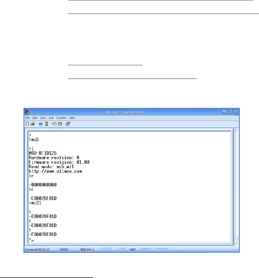
allows device configuration and reading of successfully decoded TAG IDs.
Just open the serial port assigned to MOD-RFID125 using HyperTerminal
or similar terminal program, and start typing commands.
For the impatient: type '?' and press enter to see a short help for the
supported commands. Any typed character will be echoed back; 'enter' will
force the module to process the input command line.
1.Command ?
This command prints a short help message, describing the available
commands and their arguments.
2.Command i
This command prints a short information about firmware version,
hardware board revision, and currently selected configuration.
3.Command b
This command forces the device to enter boot loader mode. After
executing this command the device will disconnect itself from USB,
switch to boot loader mode, and reconnect itself in anticipation of
receiving a firmware upgrade image. See the section “Firmware
Upgrade” for more information.
4.Command r
This command is only valid if device is in single read mode (see
below). It will trigger a single TAG read. If TAG ID is successfully
read, it will be printed. Otherwise if operation timed out, zeros will
be printed.
5.Command msXX
Set single read mode. The XX parameter must be a decimal value,
indicating the TAG read timeout in seconds.
Example – setting single read mode with 15 seconds timeout:
ms15
6.Command mcFR
Set continuous read mode with frequency F (Hz) and repeat report
interval R (seconds). Both F and R must be single digit decimal
numbers.
If F is 0 then RF antenna is constantly switched on and the device is
scans continuously for tags. Otherwise if F is 1-5, the device will
switch the antenna on F times per second.
If R is 0 then a successfully read RF tag ID is reported only once.
Otherwise if R is 1-9, the device will report the tag ID every R
seconds until the tag is seen in the proximity.
Example – continuous scanning, single report per seen tag:
mc00
Example – scan once per second, single report per seen tag:
mc10