SFR2500003009JR500

SFR16S, SFR25, SFR25H
www.vishay.com
Vishay BCcomponents
Revision: 12-Aug-16
7
Document Number: 28722
For technical questions, contact: filmresistorsleaded@vishay.com
THIS DOCUMENT IS SUBJECT TO CHANGE WITHOUT NOTICE. THE PRODUCTS DESCRIBED HEREIN AND THIS DOCUMENT
ARE SUBJECT TO SPECIFIC DISCLAIMERS, SET FORTH AT www.vishay.com/doc?91000
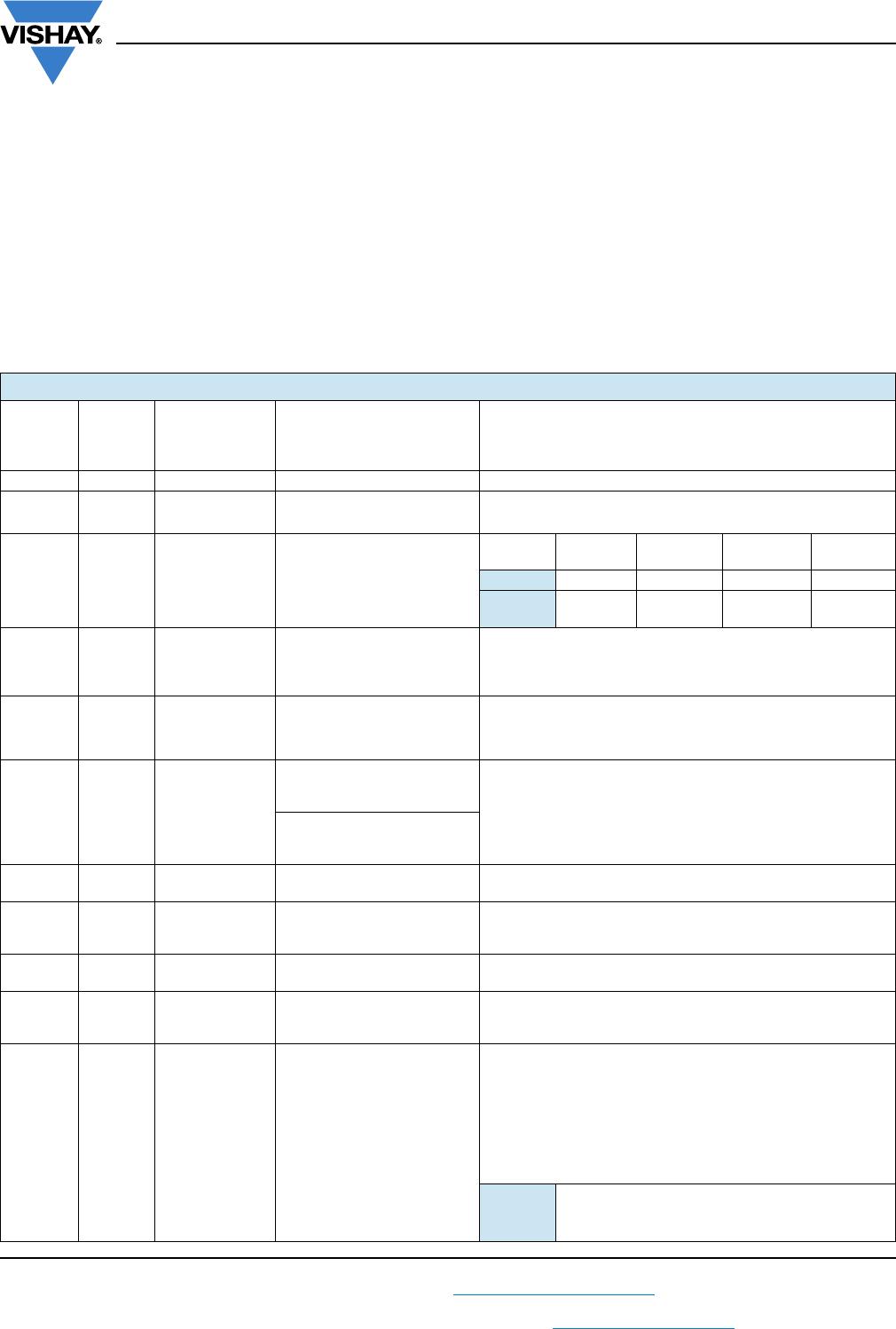
TESTS PROCEDURES AND REQUIREMENTS
All tests are carried out in accordance with the following
specifications:
EN 60115-1, generic specification (includes tests)
The test and requirements table contains only the most
important tests. For the full test schedule refer to the
documents listed above.
The tests are carried out in accordance with IEC 60068-2-xx
test method and under standard atmospheric conditions in
accordance with IEC 60068-1, 5.3.
Unless otherwise specified the following values apply:
Temperature: 15 °C to 35 °C
Relative humidity: 45 % to 75 %
Air pressure: 86 kPa to 106 kPa (860 mbar to 1060 mbar).
For performing some of the tests, the components are
mounted on a test board in accordance with IEC 60115-1,
4.31. In test procedures and requirements table, only the
tests and requirements are listed with reference to the
relevant clauses of IEC 60115-1 and IEC 60068-2-xx test
methods. A short description of the test procedure is also
given.
TEST PROCEDURES AND REQUIREMENTS
IEC
60115-1
CLAUSE
IEC
60068-2
TEST
METHOD
TEST PROCEDURE REQUIREMENTS PERMISSIBLE CHANGE (R
max.
)
4.5 - Resistance - ± 5 %; ± 1 %
4.8 -
Temperature
coefficient
At (20 / -55 / 20) °C
and (20 / 155 / 20) °C
± 250 ppm/K; ± 100 ppm/K
4.12 - Noise IEC 60195
< 68 k
68 k to
100 k
> 100 k to
1 M
> 1 M
SFR16S ≤ 0.1 μV/V ≤ 0.5 μV/V ≤ 1.5 μV/V ≤ 1.5 μV/V
SFR25,
SFR25H
≤ 0.1 μV/V ≤ 0.1 μV/V ≤ 0.1 μV/V ≤ 1.5 μV/V
4.13 -
Short time
overload
Room temperature;
P = 6.25 x P
n
;
(voltage not more than 2 x
limiting voltage); 5 s
± (0.25 %R +0.05)
4.16
21 (Ua1)
21 (Ub)
21 (Uc)
Robustness of
terminations
Tensile, bending, and torsion ± (0.25 % R + 0.05 )
4.17 20 (Ta) Solderability
at +235 °C; 2 s;
solder bath method;
SnPb40
Good tinning (≥ 95 % covered); no damage
at +245 °C; 3 s;
solder bath method;
SnAg3Cu0.5
4.18 20 (Tb)
Resistance to
soldering heat
Unmounted components
(260 ± 5) °C; (10 ± 1) s
± (0.25 % R + 0.05 )
4.19 14 (Na)
Rapid change of
temperature
30 min at -55 °C and
30 min at +155 °C;
5 cycles
± (0.25 % R + 0.05 )
4.20 29 (Eb) Bump
3 x 1500 bumps in 3 directions;
40 g
± (0.25 % R + 0.05 ); no damage
4.22 6 (Fc) Vibration
10 sweep cycles per direction;
10 Hz to2000 Hz
1.5 mm or 200 m/s
2
± (0.25 % R + 0.05 ); no damage
4.23
Climatic
sequence:
4.23.2 2 (Ba) Dry heat 155 °C; 16h
4.23.3 30 (Db)
Damp heat,
cyclic
55 °C; 24h;
90% to100%RH; 1 cycle
4.23.4 1 (Aa) Cold -55 °C; 2h
4.23.5 13 (M) Low air pressure 8.5kPa; 2h; 15 °Cto35 °C
4.23.6 30 (Db)
Damp heat,
cyclic
55°C; 5days;
95 %to100%RH; 5 cycles
SFR16S,
SFR25,
SFR25H
± (1 %R +0.05 ); no visible damage
± 2 %R; no visible damage
4.23.7 DC load apply rated power for 1 min
SFR16S, SFR25, SFR25H
www.vishay.com
Vishay BCcomponents
Revision: 12-Aug-16
8
Document Number: 28722
For technical questions, contact: filmresistorsleaded@vishay.com
THIS DOCUMENT IS SUBJECT TO CHANGE WITHOUT NOTICE. THE PRODUCTS DESCRIBED HEREIN AND THIS DOCUMENT
ARE SUBJECT TO SPECIFIC DISCLAIMERS, SET FORTH AT www.vishay.com/doc?91000
DIMENSIONS
SFR25, SFR25H WITH RADIAL TAPING
Note
• Please refer to document “Packaging” for more detail
(www.vishay.com/doc?28721
).
4.24 78 (Cab)
Damp heat
(steady state)
(40 ± 2) °C; 56 days;
(93 ± 3) % RH
± (2 % R + 0.05)
4.25.1
Endurance
(at 70 °C)
U= or U = U
max.
;
1.5 h on; 0.5 h off
70 °C; 1000 h
± (2 % R + 0.05 )
DIMENSIONS - Leaded resistor types, mass and relevant physical dimensions
TYPE
Ø D
max.
(mm)
L
1 max.
(mm)
L
2 max.
(mm)
Ø d
(mm)
MASS
(mg)
SFR16S 1.9 3.5 4.1 0.45 ±0.05 102
SFR25 2.5 6.5 7.5 0.58 ±0.05 205
SFR25H 2.5 6.5 7.5 0.58 ±0.05 205
TEST PROCEDURES AND REQUIREMENTS
IEC
60115-1
CLAUSE
IEC
60068-2
TEST
METHOD
TEST PROCEDURE REQUIREMENTS PERMISSIBLE CHANGE (R
max.
)
Ø D
L
1
Ø d
Outline
L
2
P
P
2
W
W
0
D
0
P
1
P
0
L
1
L
F
H
0
H
1
H
α = 30° to 40°
α
α
aa
DIMENSIONS in millimeters
Pitch of components P 12.7 ± 1.0
Feed-hole pitch P
0
12.7 ± 0.2
Feed-hole center to lead at topside at
the tape
P
1
3.85 ± 0.5
Feed-hole center to body center P
2
6.35 ± 1.0
Lead-to-lead distance F 4.8 + 0.7 / - 0
Tape width W 18.0 ± 0.5
Minimum hold down tape width W
0
5.5
Maximum component height H1 29
Lead wire clinch height H
0
16.5 ± 0.5
Height of component from tape center H 19.5 ± 1
Feed-hole diameter D
0
4.0 ± 0.2
Maximum length of snipped lead L 11.0
Minimum lead wire (tape portion)
shortest lead
L
1
2.5
SFR16S, SFR25, SFR25H
www.vishay.com
Vishay BCcomponents
Revision: 12-Aug-16
9
Document Number: 28722
For technical questions, contact: filmresistorsleaded@vishay.com
THIS DOCUMENT IS SUBJECT TO CHANGE WITHOUT NOTICE. THE PRODUCTS DESCRIBED HEREIN AND THIS DOCUMENT
ARE SUBJECT TO SPECIFIC DISCLAIMERS, SET FORTH AT www.vishay.com/doc?91000
HISTORICAL 12NC INFORMATION
The resistors had a 12-digit numeric code starting with 23.
The subsequent 6 digits for 1 % or 7 digits for 5 %
indicated the resistor type and packaging.
The remaining digits indicated the resistance value:
- The first 3 digits for 1 % or 2 digits for 5 % indicated the
resistance value.
- The last digit indicated the resistance decade.
Resistance Decade for ± 5 % Tolerance
Resistance Decade for ± 1 % Tolerance
12NC Example
The 12NC of a SFR25 resistor, value 5600 ± 5 %, taped
on a bandolier of 5000 units in ammopack was:
2322 181 43562.
RESISTANCE DECADE LAST DIGIT
0.10 to 0.91 7
1 to 9.1 8
10 o 91 9
100 to 910 1
1 k to 9.1 k 2
10 k to 91 k 3
100 k to 910 k 4
1 M to 9.1 M 5
= 10 M 6
RESISTANCE DECADE LAST DIGIT
1 to 9.76 8
10 to 97.6 9
100 to 976 1
1 k to 9.76 k 2
10 k to 97.6 k 3
100 k to 976 k 4
1 M to 9.76 M 5
= 10 M 6
HISTORICAL 12NC - Resistor type and packaging
TYPE TOL.
23.. ... .....
BANDOLIER IN AMMOPACK BANDOLIER ON REEL
RADIAL TAPED STRAIGHT LEADS STRAIGHT LEADS
4000 UNITS 1000 UNITS 5000 UNITS 5000 UNITS
SFR16S
± 5 % - ..22 187 73... ..22 187 53... ..06 187 23...
± 1 % - - ..06 187 3... ..06 187 1....
Jumper - - ..06 187 90013 ..22 187 90346
SFR25
± 5 % ..06 184 03... ..22 181 53... ..22 181 43... ..22 181 63...
± 1 % - - ..22 188 2... ..06 181 8....
Jumper - ..22 181 90018 ..22 181 90019 ..06 181 90011
SFR25H
± 5 % ..06 186 03... ..22 186 16... ..22 186 76... ..06 186 63...
± 1 % - - ..22 186 3.... ..06 186 8....

SFR2500003009JR500

Mfr. #:
Manufacturer:
Description:
Metal Film Resistors - Through Hole
Lifecycle:
New from this manufacturer.
Delivery:
DHL FedEx Ups TNT EMS
Payment:
T/T Paypal Visa MoneyGram Western Union