XMC-01

www.excelsys.com
Medical Power Supply
User Configurable 1U size
PLUG & PLAY POWER
next generation power solution
FEATURES & OPTIONS
• EN60601-1 3rd edition approved
• Less than 300μA leakage current
• 150µA option available
• 4000VAC isolation
• Ultra high efficiency, up to 89%
• Extra low profile: 1U height (40mm)
• Plug & Play Power - allows fast custom
configuration
• Individual output control signals
• All outputs fully floating
• Series / Parallel of multiple outputs
• Few electrolytic capacitors (all long life)
• 5V bias standby voltage provided
• Standard Xgen product options include:
Conformal Coating, Low Acoustic Noise,
Low Leakage Current, Extra Ruggedisation,
Connector, Cabling & Mounting options,
Thermal Signals and Reverse Fans. See
Section 4.10 for more information
APPLICATIONS INCLUDE
Radiological imaging
Clinical diagnostics
Medical lasers
Clinical chemistry
200W-750W
MECHANICAL SPECIFICATIONS
The XM family of medically approved power supplies provides up to 750W in a
slimline 1U package. The XM family carries the latest safety agency approvals
to EN60601-1 and UL60601-1 3rd Edition, meeting the stringent creepage and
clearance requirements in this compact package. Providing up to 8 isolated
outputs, the XM family is the most flexible power supply in its class and brings
affordable configurable power to the 200-750W medical market.
The XM family consists of 4 powerPac models in 200W, 400W, 600W and 750W power
levels. Each powerPac model may be populated with up to 4 powerMods selected from
the table of powerMods shown below. Simply select your appropriate powerPac and
powerMods to get your instant custom power solution.
This slimline product boasts unrivalled power density, providing significant system space
savings. Combined with ultra-high efficiencies, the XM family provides system designers
with flexible instant solutions that significantly shorten system design-in time.
All dimensions in mm.
Mounting Holes
4 M4 threaded holes on Base. Max screw penetration is 6mm from Base.
Fleximount Side Mounting Slots
Use with self-clinching studs type FH-M4-X or FH-832-X (X= stud length) from PEM, or equivalent
Alternatively, use Xgen Side Clamps from Excelsys. Part No. Z165 (drawing 61401)
J1
J2
INPUT AC 100V-240V 50/60Hz
SEE INSTRUCTION MANUAL
70C MAX OPERATING TEMPERATURE
29.50
40.40
122.00
46.00
23.50
23.50
42.00
92.00
19.00 89.00
SLOT D
SLOT C
SLOT B
SLOT A
Third angle projection
TOP VIEW
50.00
97.75
M
XM
powerPacs
MODEL Watts
XMA 200W
XMB 400W
XMC 600W
XMD 750W
All dimensions in mm.
Mounting Holes
4 M4 threaded holes on Base. Max screw penetration is 6mm from Base.
Fleximount Side Mounting Slots
Use with self-clinching studs type FH-M4-X or FH-832-X (X= stud length) from PEM, or equivalent
Alternatively, use Xgen Side Clamps from Excelsys. Part No. Z165 (drawing 61401)
J1
J2
INPUT AC 100V-240V 50/60Hz
SEE INSTRUCTION MANUAL
70C MAX OPERATING TEMPERATURE
29.50
40.40
122.00
23.50
23.50
42.00
92.00
19.00 89.00
SLOT D
SLOT C
SLOT B
SLOT A
Third angle projection
TOP VIEW
54.00
97.75
XMA, XMB, XMC
XMD
Slimline Medical
Series
Note: See diagrams on pages 34-37
powerMods
MODEL Vmin Vnom Vmax Imax Watts
Vtrim Vpot
Xg1 1.0 1.5 2.5 3.6 50A 125W
Xg2 1.5 3.2 5.0 6.0 40A 200W
Xg3 4.0 6.0 12.0 15.0 20A 240W
Xg4 8.0 12.0 24.0 30.0 10A 240W
Xg5 8.0 24.0 48.0 58.0 6A 288W
Xg7 5.0 24.0 28.0 5A 120W
Xg8 V1 5.0 24.0 28.0 3A 72W
V2 5.0 24.0 28.0 3A 72W
www.excelsys.com
Slimline Medical
NOTES 1. This product is not intended for use as a stand alone unit and must be installed by qualified personnel.
2. The specifications contained herein are believed to be correct at time of publication and are subject to change without notice.
3. All specifications at nominal input, full load, 25°C unless otherwise stated.
4. XMD: 800W peak for 1s; Duty cycle 7%. powerMod output power must not exceed normal ratings.
5. When powering inductive or capacitive loads, it is recommended to use a blocking diode on the output.
6. For section references above go to the Xgen Designers Manual.
200W-750W
SPECIFICATION applies to configured units consisting of powerMods plugged into the appropriate powerPac
INPUT
Parameter Conditions/Description Min Nom Max Units
Input Voltage Range Universal Input 47-63Hz. Contact factory for 440Hz operation 85 264 VAC
120 380 VDC
Power Rating XMA:200W, XMB:400W, XMC:600W, XMD:750W
See Section 4.11 for line voltage deratings
Input Current XMA 85VAC in 200W out 4.0 A
XMB 85VAC in 400W out 6.0 A
XMC 85VAC in 400W out 7.5 A
XMD 85VAC in 525W out 7.5 A
Inrush Current 230VAC, 25°C 50 A
Undervoltage Lockout Shutdown 65 74 VAC
Fusing XMA 250V 5 x 20mm F5A HRC
XMB 250V 5 x 20mm F6.3A HRC
XMC, XMD 250V 5 x 20mm F8A HRC
OUTPUT
P
arameter Conditions/Description Min Nom Max Units
powerMod Power As per powerMod table
Output Adjustment Range Manual: Multi-turn potentiometer. As per powerMod table
Electronic: See Section 4.6
Minimum Load 0A
Line Regulation For ±10% change from nominal line ±0.1 %
Load Regulation For 25% to 75% load change ±0.2 %
Cross Regulation ±0.2 %
Transient Response For 25% to 75% load change Voltage Deviation 10 %
Settling Time 250 µs
Ripple and Noise 20MHz 100mV or 1.0% pk-pk
Overvoltage Protection 1st level: Vset Tracking. 2nd level: Vmax (Latching) 110 125 %
Overcurrent Protection Straight line with hiccup activation at <30% of Vnom 110 120 %
See Section 4.6
Remote Sense Max. line drop compensation. (except Xg7, Xg8) 0.5 VDC
Overshoot 2%
Turn-on Delay From AC In / Enable signal XMA, XMB, XMC 600 / 30 ms
From AC In / Enable signal XMD 1000/30 ms
Rise Time Monotonic 5 ms
Hold-up Time For nominal output voltages at full load XMA,XMB, XMC/XMD 20/15 ms
Output Isolation Output to Output / Output to Chassis 500 / 500 VDC
GENERAL
Parameter Conditions/Description Min Nom Max Units
Isolation Voltage Input to Output 4000 VAC
Input to Chassis 1500 VAC
Efficiency 230VAC, 750W @ 24V 89 %
Safety Agency Approvals EN60601-1, UL60601-1 3rd Edition, CSA601-1 UL File no. E230761
Leakage Current 250VAC, 60Hz, 25°C 300 µA
250VAC, 60Hz, 25°C Option 04 150 µA
Signals See Section 4.9
Bias Supply Always on. Current 250mA. 500mA option available 4.8 5.0 5.2 VDC
Reliability Failures per million hours at 25°C and full load powerMod 0.98 fpmh
See Section 4.12. powerPac excludes fans powerPac 0.92 fpmh
EMC
Parameter Standard Level Units
Emissions
Conducted EN55011, EN55022, FCC Level B
Radiated EN55011, EN55022, FCC Level B
Harmonic Distortion EN61000-3-2 Class A Compliant
Flicker & Fluctuation EN61000-3-3 Compliant
Immunity
Electrostatic Discharge EN61000-4-2 Level 2
Radiated Immunity EN61000-4-3 Level 3
Fast Transients-Burst EN61000-4-4 Level 3
Input Line Surges EN61000-4-5 Level 3
Conducted Immunity EN61000-4-6 Level 3
Voltage Dips EN61000-4-11 Compliant
ENVIRONMENTAL
Parameter Conditions/Description Min Nom Max Units
Operating Temperature -20 +70 °C
Storage Temperature -40 +85 °C
Derating See Section 4.11 for full temperature deratings
Relative Humidity Non-condensing 5 95 %RH
Shock 3000 Bumps, 10G (16ms) half sine
Vibration 1.5G 10 200 Hz
www.excelsys.com
For detailed information please refer to the Xgen Designers’
Manual which is available on-line or contact Excelsys.
Voltage Adjustment
Output voltage can be adjusted in a number of ways:
1. On board multi turn potentiometer
2. Remote resistive programming (via Vtrim pin)
3. Remote voltage programming (via Vtrim pin)
Current Limit Adjustment
Output current limit can be Straight line or Foldback and can be
adjusted via Itrim pin.
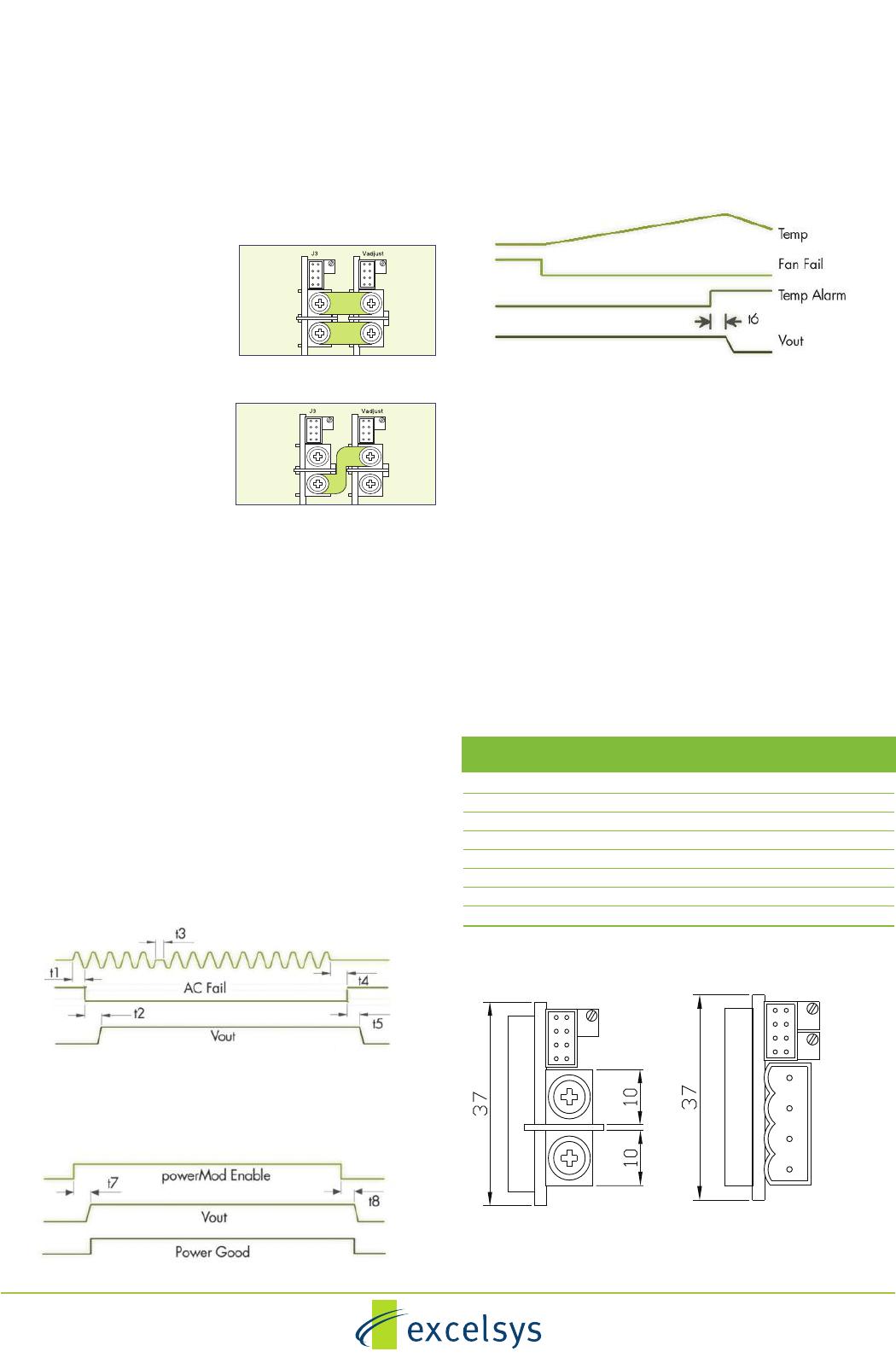
Parallel Connection
To achieve increased current
capacity, simply parallel outputs
using the standard parallel links.
Series Connection
To achieve increased output
voltages, simply series outputs
using standard series links,
paying attention to the
requirements to maintain SELV
levels if required in your system.
Remote Sensing
When the load is remote from the power supply, the remote
sense pins may be used to compensate for drops in the power
leads. Where the power cabling contributes significant dynamic
impedance, see Xgen series Designers’ Manual.
Bias Voltage
A SELV isolated bias (always on) voltage of 5V @ 250mA
(30mA on XCE and XVE models) is provided on J2 pin 2 relative
to J2 pin 1 (common) and may be used for miscellaneous
control functions. 5V @ 500mA available on request.
Inhibit/Enable
Inhibiting may be implemented either globally or on a per
module basis (powerPac or powerMod inhibiting). Reverse logic
(enabling) may also be implemented.
AC Fail
Open collector signal indicating that the input voltage has failed
or is less thant 80Vac. This signal changes state giving 5ms of
warning beore loss of output regulation.
Power Good
Opto-isolated output signal indicates that the powerMod is
operating correctly and output voltage is within normal band.
powerPac Options
Temperature Alarm (Option 01)
Open collector signal indicating that excessive temperature has
been reached due to fan failure or operation beyond ratings. This
signal is activated at least 10ms prior to system shutdown.
Fan Fail (Option 01)
Open collector signal indicating that at least one of the
powerPac fans has failed. This does not cause power supply
shutdown. The power supply will continue to operate until 10ms
after the temperature alarm signal is generated.
Reverse Fan (Option 02)
The Xgen series is available with reverse air flow direction.
Contact Excelsys for derating details.
Ultra Low Leakage current (Option 04)
The Xgen is available with the option of Ultra Low Earth Leakage
Current of <150μA and is approved to EN60601-1 and
UL60601-1 2nd and 3rd Editions.
Conformal Coating (Option C)
Xgen is available with conformal coating for harsh environments
and MIL-COTs applications.
Ruggedised Option (Option R)
Xgen is available with extra ruggedisation for applications that
are subject to extremes in shock and vibration.
Input cable Option (Option D)
3 Wire input mains cable. Input cables are 300mm in length and
come supplied with fast on connectors.
Parallel Links available to order.
Part Number XP1
J3
J4
Voltage
Adjust
M4 Screws
2 1
2
1
J4 Connector : M4 Screw
J3 Connector Mating Connector
Housing: Locking Molex 51110-0860
Non Locking Molex 51110-0850
Crimp Termnal: Molex p/n 50394
J4Connector : Camden 9200/4A
J3 Connector Mating Connector
Housing: Locking Molex 51110-0860
Non Locking Molex 51110-0850
Crimp Termnal: Molex p/n 50394
J3
J4
V1 Adjust
2 1
1
3
4
2
V2 Adjust
TYPE A Xg1-Xg7 TYPE B : Xg8
Series Links available. Part
Number XS1
Xgen Flexibility and Signals
Signal Connector Pinout
Pin J2 (powerPac) J3 (powerMod) J3 (powerMod)
Type A Type B
1 common +sense +pg (V2)
2 +5V bias -sense -pg (V2)
3 V trim inhibit (V2)
4 ac fail I trim common (V2)
5 fan fail* +inhibit/enable +pg (V1)
6 global enable -inhibit/enable -pg (V1)
7 temp alarm* +power good inhibit (V1)
8 global inhibit -power good common (V1)
*Option 01 only

XMC-01

Mfr. #:
Manufacturer:
Description:
CONFIG POWER CHASSIS 600W 4 SLOT
Lifecycle:
New from this manufacturer.
Delivery:
DHL FedEx Ups TNT EMS
Payment:
T/T Paypal Visa MoneyGram Western Union

Products related to this Datasheet