IDT
®
Six Output Differential Buffer for PCIe Gen3 1668F—10/20/16
9DB633
Six Output Differential Buffer for PCIe Gen3
4
Datasheet
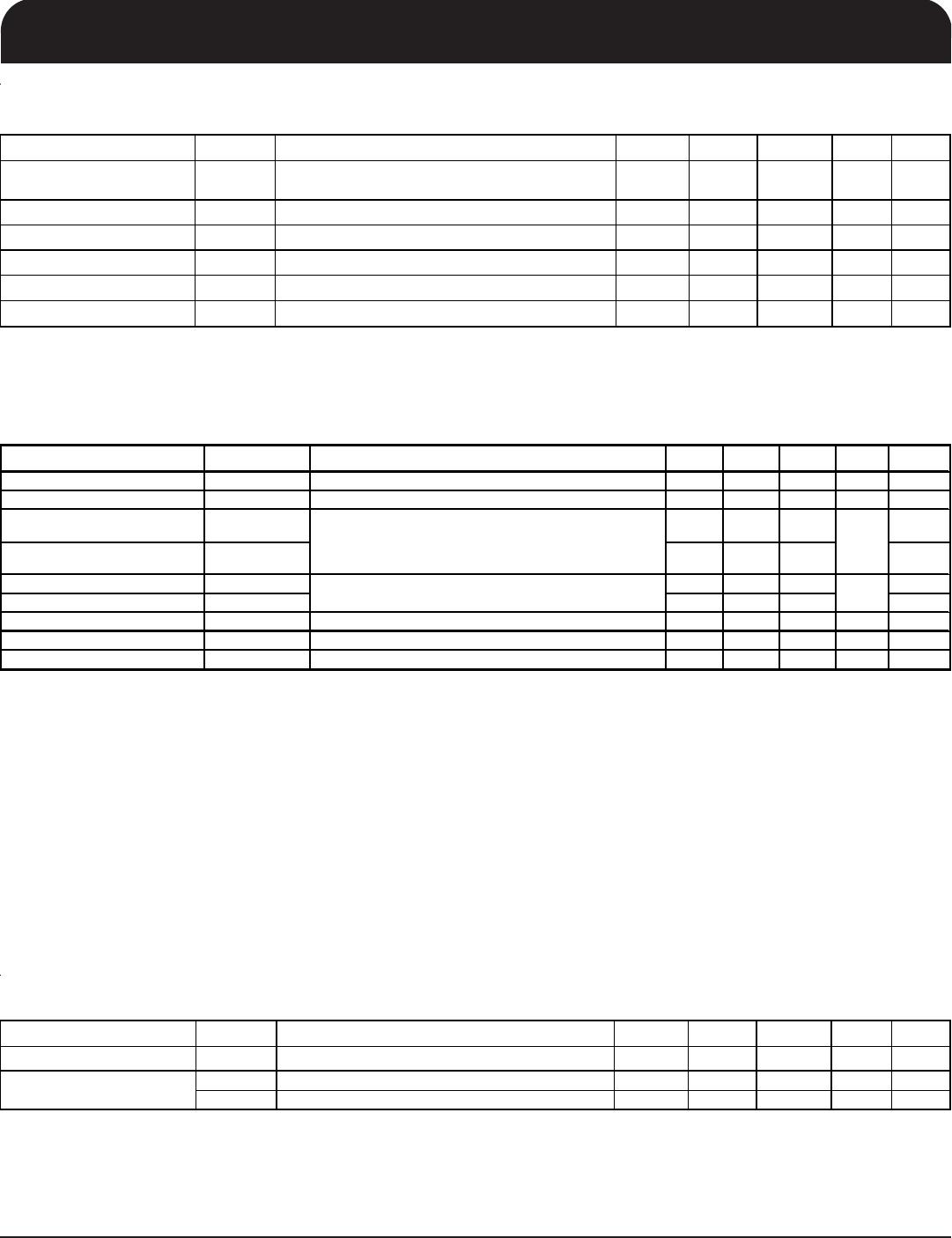
Electrical Characteristics - Absolute Maximum Ratings
PARAMETER SYMBOL CONDITIONS
MIN TYP MAX
UNITS NOTES
3.3V Core Supply Voltage VDDA 4.6 V 1,2
3.3V Logic Supply Voltage VDD 4.6 V 1,2
Input Low Voltage V
IL
GND-0.5 V 1
Input High Voltage V
IH
Except for SMBus interface V
D
+0.5V V 1
Input High Voltage V
IHSMB
SMBus clock and data pins 5.5V V 1
Storage Temperature Ts -65 150
°
C
1
Junction Temperature Tj 125 °C 1
Input ESD protection
ESD prot Human Body Model 2000 V 1
1
Guaranteed by design and characterization, not 100% tested in production.
2
Operation under these conditions is neither implied nor guaranteed.
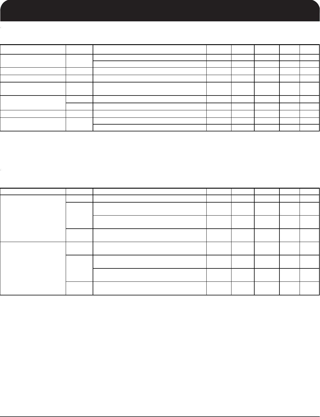
Electrical Characteristics - Input/Supply/Common Parameters
TA = T
CO M
or T
IND
Supply Voltage VDD = 3.3 V +/-5%
PARAMETER SYMBOL CONDITIONS MIN TYP MAX UNITS NOTES
T
COM
Commmercial range 0 70 °C 1
T
IND
Industrial range -40 85 °C 1
Input High Voltage V
IH
Single-ended inputs, except SMBus, low
threshold and tri-level inputs
2V
DD
+ 0.3 V 1
Input Low Voltage V
IL
Single-ended inputs, except SMBus, low
threshold and tri-level inputs
GND
- 0.3 0.8 V 1
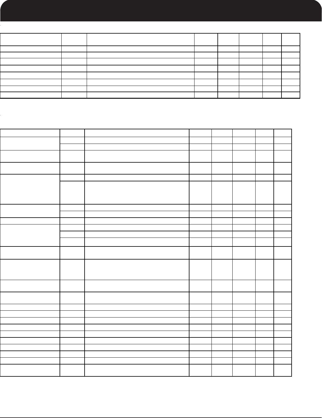
I
IN
Single-ended inputs, V
IN
= GND, V
IN
= VDD -5 5 uA 1
I
INP
Single-ended inputs
V
IN
= 0 V; Inputs with internal pull-up resistors
V
IN
= VDD; Inputs with internal pull-down resistors
-200 200 uA 1
F
ibyp
V
DD
= 3.3 V, Bypass mode 10 110 MHz 2
F
ipll
V
DD
= 3.3 V, 100MHz PLL mode 33 100.00 110 MHz 2
Pin Inductance L
pin
7nH1
C
IN
Logic Inputs, except DIF_IN 1.5 5 pF 1
C
INDIF_IN
DIF_IN differential clock inputs 1.5 2.7 pF 1,4
C
OUT
Output pin capacitance 6 pF 1
Clk Stabilization T
STAB
From V
DD
Power-Up and after input clock
stabilization or de-assertion of PD# to 1st clock
1.8 ms 1,2
Input SS Modulation
Frequency
f
MODI N
Allowable Frequency
(Triangular Modulation)
30 33 kHz 1
OE# Latency t
LATOE#
DIF start after OE# assertion
DIF stop after OE# deassertion
1 3 cycles 1,3
Tdrive_PD# t
DRVPD
DIF output enable after
PD# de-assertion
300 us 1,3
Tfall t
F
Fall time of control inputs 5 ns 1,2
Trise t
R
Rise time of control inputs 5 ns 1,2
SMBus Input Low Voltage V
ILSMB
0.8 V 1
SMBus Input High Voltage V
IHSMB
2.1 V
DDSMB
V1
SMBus Output Low Voltage V
OLSMB
@ I
PULLUP
0.4 V 1
SMBus Sink Current I
PULLUP
@ V
OL
4mA1
Nominal Bus Voltage V
DDSMB
3V to 5V +/- 10% 2.7 5.5 V 1
SCLK/SDATA Rise Time t
RSMB
(Max VIL - 0.15) to (Min VIH + 0.15) 1000 ns 1
SCLK/SDATA Fall Time t
FSMB
(Min VIH + 0.15) to (Max VIL - 0.15) 300 ns 1
SMBus Operating
Frequency
f
MAXSMB
Maximum SMBus operating frequency 100 kHz 1,5
1
Guaranteed by design and characterization, not 100% tested in production.
2
Control input must be monotonic from 20% to 80% of input swing.
5
The differential in
ut clock must be runnin
for the SMBus to be active
Ambient Operating
Temperature
Input Current
3
Time from deassertion until out
uts are >200 mV
4
DIF_IN input
Capacitance
Input Frequency