DC FILTERING
30 ■ JUNE 2015
Medium Power Film Capacitors
FFLI 800V to 1400Vdc (RoHS Compliant)
The FFLI series is specifically designed for DC filtering applications such as DC link.
This range offers solutions for voltage from 800V up to 1400V.
The Controlled Self Healing Technology, essential to ensure a safe and
reliable behaviour, is achieved using a fully dry solution with polypropylene
metallized and segmented film. Standard designs proposed in this catalogue
are covering a wide range of voltage and capacitance values.
In case of specific requirements about shape and performances, please feel
free to contact your local AVX representative.
PACKAGING MATERIAL
Aluminium cylindrical case filled polyurethane resin.
Self extinguishing polyurethane resin (V0 : in accordance with UL94; M2F1:
in accordance with NF F 16-101)
Self extinguishing plastic cover (V0 : in accordance with UL94)
RoHS components
M6/10 Female connections or M8/20 Male connections
STANDARDS
IEC 61071: Power electronic capacitors
IEC 61881: Railway applications, rolling stock equipment, capacitors
for power electronics
IEC 60068-2: Environmental testing
IEC 61373: Shock and vibrations
UL 94: Fire requirements
HOW TO ORDER
DEFINITIONS
FFLI
Series
6
Dielectric
6 = Polypropylene
L
Voltage
Code
B = 800V
L = 1000V
U = 1150V
Q = 1400V
0337
Capacitance
EIA Code
K
Capacitance
Tolerances
K = ±10%
––
Terminal Code
– – = Male Threaded
JE = Female Threaded
C
n
(μF) capacitance nominal value of the capacitance measured at
θ
amb
= 25
±
10°C
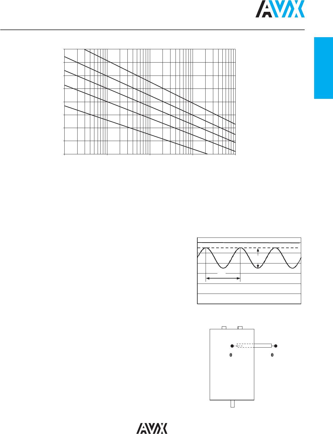
maximum operating peak voltage of either polarity (non-reversing
U
n
(V) rated DC voltage type waveform), for which the capacitor has been designed for
continuous operation
U
w
(V) working voltage
value of the maximum operating recurrent voltage for a given hot
spot temperature and an expected lifetime
U
r
(V) ripple voltage peak-to-peak alternating component of the unidirectional voltage
L
s
(nH) parasitic inductance capacitor series self-inductance
R
s
(mΩ) series resistance capacitor series resistance due to galvanic circuit
I
rms
(A) RMS current
RMS current value for continuous operation under natural
convection generating 40°C overheating
temperature of the cooling air measured at the hottest position of
the capacitor, under steady-state conditions, midway between
θ
amb
(°C) cooling air temperature two units
NOTE If only one unit is involved, it is the temperature measured
at a point approximately 0.1 m away from the capacitor container and at two-thirds of
the height from its base
θ
HS
(°C) hot spot temperature
highest temperature obtained inside the case of the capacitor in
thermal equilibrium
I²t (A²s) integral of action
maximum repetitive integral of action that galvanic circuit is able to
withstand
CHARACTERISTICS
Capacitance range C
n
105μF to 3000μF
Tolerance on C
n
±10%
Rated DC voltage U
n
800 to 1400V
Lifetime at U
n
and 65°C
hot-spot temperature 100,000h
and
Δ
C / C < 2%
Parasitic inductance L
s
35 to 60nH
Maximum rms current I
rms
up to 112A
rms
Test voltage between terminals
1.5 x U
n
for 10s
@ 25°C
Test voltage between terminals 4kV
rms
@ 50Hz
and Case @ 25°C for 10s
Dielectric polypropylene
Climatic Category
40 / 95 / 56
(IEC 60068)
Working temperature
-40°C / +95°C
(according to the
power dissipated)
Storage temperature -40°C / +85°C
Calorific value 40 MJ/kg