MARCH 28, 2017 7 1.8V TO 3.3V LVCMOS HIGH PERFORMANCE CLOCK BUFFER FAMILY
5PB11xx DATASHEET
Notes:
1. With rail to rail input clock
2. Between any 2 outputs with equal loading.
3. Duty cycle on outputs will match incoming clock duty cycle. Consult IDT for tight duty cycle clock generators.
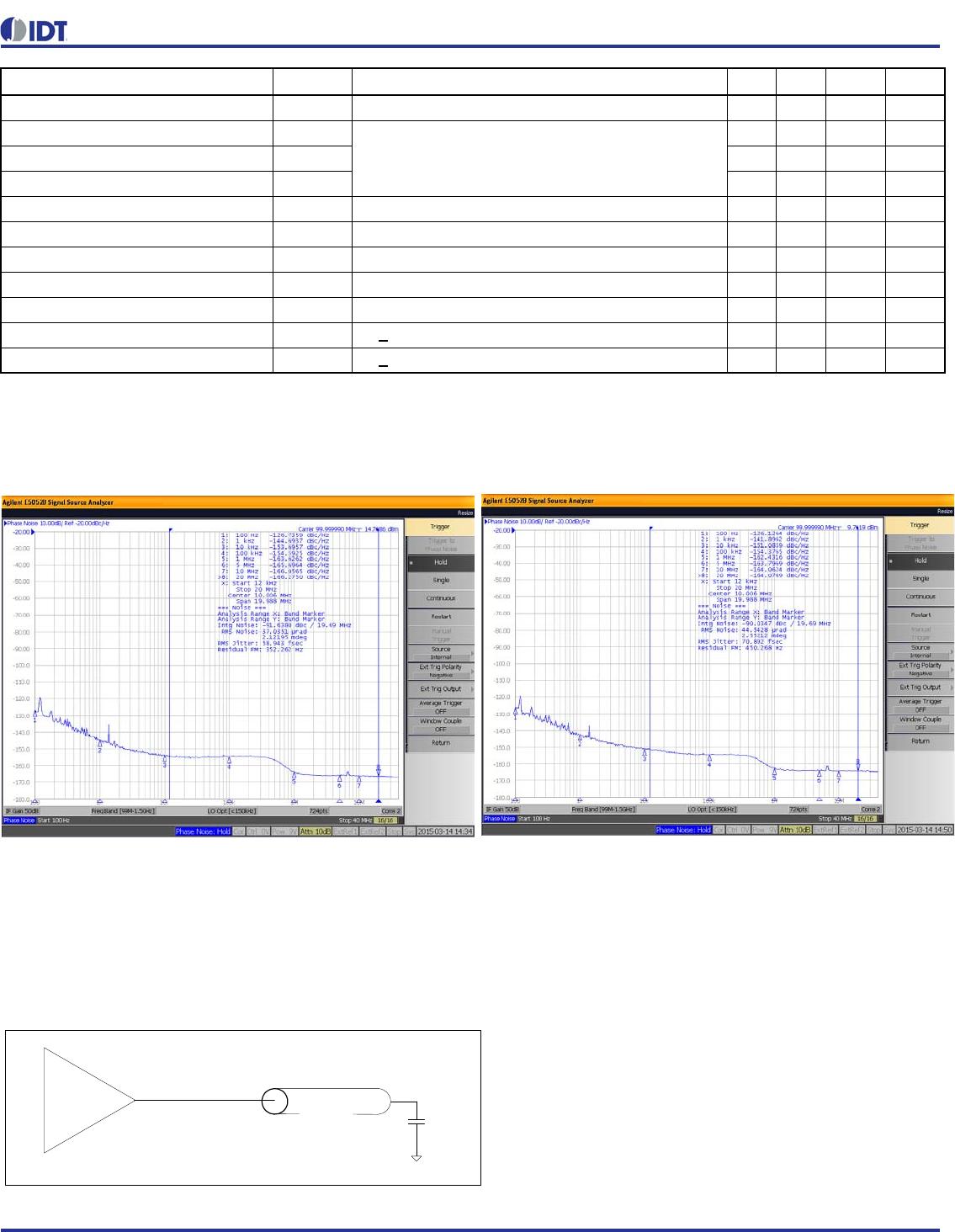
Phase Noise Plots
The phase noise plots above show the low additive jitter of the 5PB11xx high-performance buffer. With an integration range of
12kHz to 20MHz, the reference input has about 58.9fs of RMS phase jitter while the output of 5PB11xx has about 70.9fs of RMS
phase jitter. This results in a low additive phase jitter of only 39fs.
Test Load and Circuit
Start-up Time t
START-UP
Part start-up time for valid outputs after VDD ramp-up 3 ms
Propagation Delay (5PB1102/04)
Note 1
1.7 2 2.4 ns
Propagation Delay (5PB1106/08) 1.7 2 2.7 ns
Propagation Delay (5PB1110) 1.7 2 2.5 ns
Buffer Additive Phase Jitter, RMS 156.25MHz, Integration Range: 12kHz-20MHz 0.05 ps
Output to Output Skew (5PB1102/04) Rising edges at VDD/2, Note 2 35 50 ps
Output to Output Skew (5PB1106) Rising edges at VDD/2, Note 2 35 58 ps
Output to Output Skew (5PB1108/10) Rising edges at VDD/2, Note 2 45 65 ps
Device to Device Skew Rising edges at VDD/2 200 ps
Output Enable Time t
EN
C
L
< 5pF 3 cycles
Output Disable Time t
DIS
C
L
< 5pF 3 cycles
Parameter Symbol Conditions Min. Typ. Max. Units
Figure 1. 5PB11xx Reference Phase Noise 58.9fs
(12kHz to 20MHz)
Figure 2. 5PB11xx Output Phase Noise 70.9fs
(12kHz to 20MHz)
5
i
n
c
h
e
s
CL = 5pF
50ohms