3
LT1462/LT1463
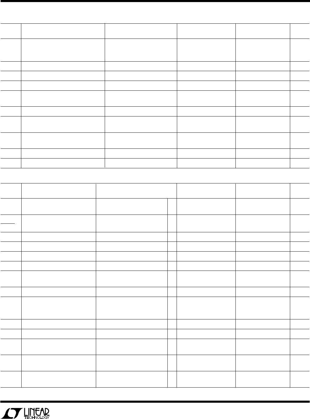
ELECTRICAL CHARACTERISTICS
V
S
= ±15V, V
CM
= 0V, T
A
= 25°C, unless otherwise noted.
V
S
= ±15V, V
CM
= 0V, 0°C ≤ T
A
≤ 70°C, unless otherwise noted.
LT1462AC LT1462C/LT1463C
SYMBOL PARAMETER CONDITIONS (Note 1) MIN TYP MAX MIN TYP MAX UNITS
V
OUT
Output Voltage Swing R
L
= 10k ±13.5 ±13.7 ±13.5 ±13.7 V
R
L
= 2k ±11.0 ±12.4 ±11.0 ±12.4 V
V
S
= ±5V, R
L
= 2k ±3.5 ±3.7 ±3.5 ±3.7 V
I
O
Output Current ±13 ±17 ±13 ±17 mA
SR Slew Rate R
L
= 10k (Note 4) 0.08 0.13 0.08 0.13 V/µs
GBW Gain Bandwidth Product f = 10kHz 125 175 125 175 kHz
I
S
Supply Current per Amplifier 28 45 28 45 µA
V
S
= ±5V 26 43 26 43 µA
Channel Separation f = 10Hz, V
O
= ±10V, R
L
= 10k 132 132 dB
V
OS
Offset Voltage Match (Note 7) V
S
= ±5V 0.5 1.3 0.5 1.3 mV
V
S
= ±15V 0.8 3.0 0.8 3.0 mV
∆I
B
+
Noninverting Bias Current Match V
S
= ±5V 0.4 3.0 pA
(Note 7) V
S
= ±15V 0.5 4.0 0.5 20 pA
∆CMRR Common Mode Rejection Match (Notes 5, 7) 74 85 72 85 dB
∆PSRR Power Supply Rejection Match (Notes 5, 7) 78 88 76 88 dB
LT1462AC LT1462C/LT1463C
SYMBOL PARAMETER CONDITIONS (Note 1) MIN TYP MAX MIN TYP MAX UNITS
V
OS
Input Offset Voltage V
S
= ±5V ● 0.5 1.4 0.5 1.4 mV
V
S
= ±15V ● 0.9 2.8 0.9 2.8 mV
∆V
OS
Average Input Offset Voltage Drift (Note 6) ● 720 720µV/°C
∆Temp
I
OS
Input Offset Current ● 10 50 25 450 pA
I
B
Input Bias Current ● 60 150 150 750 pA
CMRR Common Mode Rejection Ratio V
CM
= –12V to 15V ● 75 88 72 88 dB
PSRR Power Supply Rejection Ratio V
S
= ±3V to ±20V ● 80 89 76 89 dB
A
VOL
Large-Signal Voltage Gain V
O
= ±10V, R
L
= 10k ● 90 600 90 600 V/mV
V
S
= ±5V, V
O
= ±2V, R
L
= 2k ● 45 140 45 140 V/mV
I
O
Output Current ● ±11 ±14 ±11 ±14 mA
V
OUT
Output Voltage Swing R
L
= 10k ● ±13.4 ±13.6 ±13.4 ±13.6 V
R
L
= 2k ● ±10.5 ±12.1 ±10.5 ±12.1 V
V
S
= ±5V, R
L
= 2k ● ±3.4 ±3.6 ±3.4 ±3.6 V
SR Slew Rate R
L
= 10k (Note 4) ● 0.075 0.128 0.075 0.128 V/µs
GBW Gain Bandwidth Product f = 10kHz ● 100 140 100 140 kHz
I
S
Supply Current per Amplifier ● 31 45 31 45 µA
V
S
= ±5V ● 28 43 28 43 µA
V
OS
Offset Voltage Match (Note 7) V
S
= ±5V ● 0.7 2.0 0.7 2.0 mV
V
S
= ±15V ● 0.9 3.5 0.9 3.5 mV
∆I
B
+
Noninverting Bias Current Match ● 5 40 35 500 pA
(Note 7)