10
LTC2900
2900f
APPLICATIO S I FOR ATIO
WUUU
Figure 6. Setting the Negative Adjustable Trip Point
+
2900 F06
V4
V
REF
9
8
V
TRIP
R4
1%
R3
1%
LTC2900
sensed and ground, is connected to the high impedance
noninverting inputs (V3, V4). The trip voltage is calculated
from:
VV
R
R
TRIP
=+
05 1
3
4
.
In the negative adjustable mode, the noninverting input on
the V4 comparator is connected to ground (Figure 6). The
tap point on an external resistive divider, connected be-
tween the negative voltage being sensed and the V
REF
pin,
is connected to the high impedance inverting input (V4).
V
REF
provides the necessary level shift required to operate
at ground. The trip voltage is calculated from:
VV
R
R
V V No al
TRIP REF REF
=
= ; . min
3
4
1 210
In a negative adjustable application, the minimum value
for R4 is limited by the sourcing capability of V
REF
(±1mA).
With no other load on V
REF
, R4 (minimum) is:
1.21V ÷ 1mA = 1.21k.
Tables 2 and 3 offer suggested 1% resistor values for
various adjustable applications.
Table 2. Suggested 1% Resistor Values for the ADJ Inputs
V
SUPPLY
(V) V
TRIP
(V) R3 (k) R4 (k)
12 11.25 2150 100
10 9.4 1780 100
8 7.5 1400 100
7.5 7 1300 100
6 5.6 1020 100
5 4.725 845 100
3.3 3.055 511 100
3 2.82 464 100
2.5 2.325 365 100
1.8 1.685 237 100
1.5 1.410 182 100
1.2 1.120 124 100
1 0.933 86.6 100
0.9 0.840 68.1 100
Table 3. Suggested 1% Resistor Values for the –ADJ Input
V
SUPPLY
(V) V
TRIP
(V) R3 (k) R4 (k)
2 –1.87 187 121
5 4.64 464 121
5.2 4.87 487 121
–10 9.31 931 121
–12 –11.30 1130 121
Figure 5. Setting the Positive Adjustable Trip Point
+
+
0.5V
2900 F05
V3 OR V4
V
TRIP
R3
1%
R4
1%
LTC2900
11
LTC2900
2900f
APPLICATIO S I FOR ATIO
WUUU
Although all four supply monitor comparators have built-
in glitch immunity, bypass capacitors on V1 and V2 are
recommended because the greater of V1 or V2 is also the
V
CC
for the device. Filter capacitors on the V3 and V4
inputs are allowed.
Power-Down
On power-down, once any of the V
X
inputs drop below
their threshold, RST is held at a logic low. A logic low of
0.4V is guaranteed until both V1 and V2 drop below 1V. If
the bandgap reference becomes invalid (V
CC
< 2V typ), the
part will reprogram once V
CC
rises above 2.4V max.
Monitor Output Rise and Fall Time Estimation
The RST output has strong pull-down capability. If the
external load capacitance (C
LOAD
) is known, output fall
time (10% to 90%) is estimated using:
t
FALL
2.2 • R
PD
• C
LOAD
where R
PD
is the on-resistance of the internal pull-down
transistor. The typical performance curve (V
OL
vs I
SINK
)
demonstrates that the pull-down current is somewhat
linear versus output voltage. Using the 25°C curve, R
PD
is
estimated to be approximately 40. Assuming a 150pF
load capacitance, the fall time is about 13.2ns.
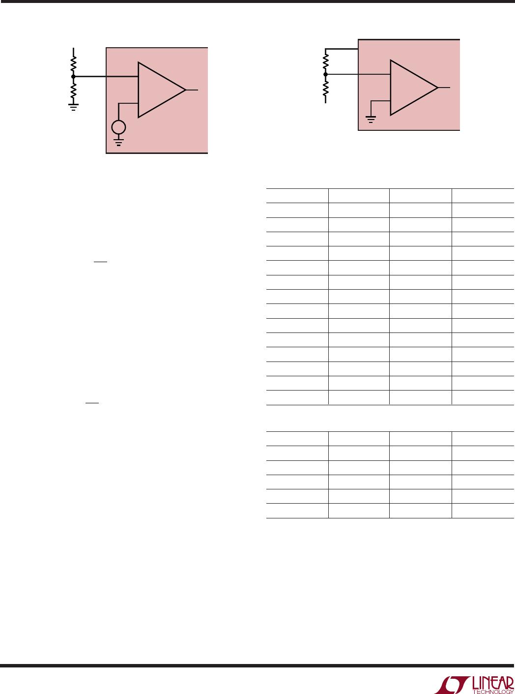
Although the RST output of the LTC2900-1 is considered
to be “open-drain,” it does have weak pull-up capability
(see RST Pull-Up Current vs V2 curve). Output rise time
(10% to 90%) is estimated using:
t
RISE
2.2 • R
PU
• C
LOAD
where R
PU
is the on-resistance of the pull-up transistor.
The on-resistance as a function of the V2 voltage at room
temperature is estimated using:
R
V
PU
=Ω
610
21
5
with V2 = 3.3V, R
PU
is about 260k. Using 150pF for load
capacitance, the rise time is 86µs. If the output needs to
pull up faster and/or to a higher voltage, a smaller
external pull-up resistor may be used. Using a 10k pull-
up resistor, the rise time is reduced to 3.3µs for a 150pF
load capacitance.
The LTC2900-2 has an active pull-up to V2 on the RST
output. The typical performance curve (RST Pull-Up Cur-
rent vs V2 curve) demonstrates that the pull-up current is
somewhat linear versus the V2 voltage and R
PU
is esti-
mated to be approximately 625. A 150pF load capaci-
tance makes the rise time about 206ns.
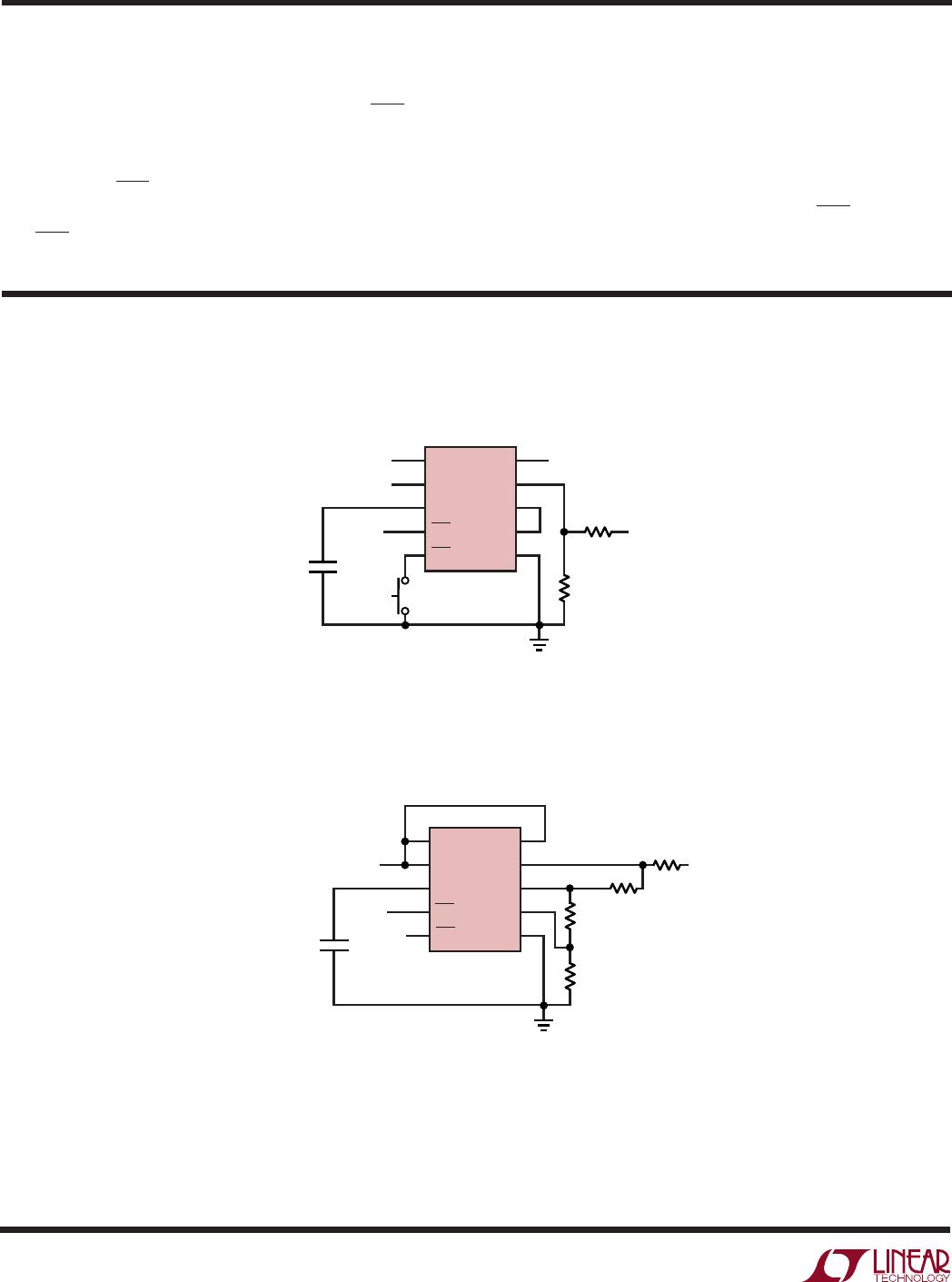
Selecting the Reset Timing Capacitor
The reset time-out period is adjustable in order to accom-
modate a variety of microprocessor applications. The
reset time-out period, t
RST
, is adjusted by connecting a
capacitor, C
RT
, between the CRT pin and ground. The value
of this capacitor is determined by:
C
RT
= t
RST
• 217 • 10
–9
with C
RT
in Farads and t
RST
in seconds. The C
RT
value per
millisecond of delay can also be expressed as C
RT
/ms =
217 (pF/ms).
Leaving the CRT pin unconnected will generate a mini-
mum reset time-out of approximately 50µs. Maximum
reset time-out is limited by the largest available low
leakage capacitor. The accuracy of the time-out period will
be affected by capacitor leakage (the nominal charging
current is 2µA) and capacitor tolerance. A low leakage
ceramic capacitor is recommended.
12
LTC2900
2900f
TYPICAL APPLICATIO S
U
Quad Supply Monitor with Push-Button Reset
5V, 3V, 1.8V, 12V (ADJ)
V3
V1
CRT
RST
PBR
V2
V4
V
REF
V
PG
GND
5
NORMALLY
OPEN
C
RT
3V
12V
SYSTEM
RESET
R4
100k
1%
R3
2.15M
1%
4
6
7
8
9
10
3
2
1
1.8V
5V
V
TRIP
= 11.25V
LTC2900
2900 TA02
5V, –5V Monitor and Unused V2, V3 Inputs
Pulled Above Trip Thresholds
V3
V1
CRT
RST
PBR
V2
V4
V
REF
V
PG
GND
5
C
RT
SYSTEM
RESET
–5V
R3
464k
1%
R4
121k
1%
R2
86.6k
1%
R1
16.2k
1%
4
6
7
8
9
10
3
2
1
5V
LTC2900
2900 TA03
V
TRIP
= –4.64V
Ensuring Reset Valid for V
CC
Down to 0V (LTC2900-2)
Some applications require the reset output (RST) to be
valid with V
CC
down to 0V. The LTC2900-2 is designed to
handle this requirement with the addition of an external
resistor from RST to ground. The resistor will provide a
path for stray charge and/or leakage currents, preventing
the RST output from floating to undetermined voltages
when connected to high impedance (such as CMOS logic
inputs). The resistor value should be small enough to
provide effective pull-down without excessively loading
the active pull-up circuitry. Too large a value may not pull
down well enough. A 100k resistor from RST to ground is
satisfactory for most applications.
APPLICATIO S I FOR ATIO
WUUU

LTC2900-1IDD#TRPBF

Mfr. #:
Manufacturer:
Analog Devices Inc.
Description:
Supervisory Circuits Quad Voltage Monitor
Lifecycle:
New from this manufacturer.
Delivery:
DHL FedEx Ups TNT EMS
Payment:
T/T Paypal Visa MoneyGram Western Union