G3VM-351E

1
G3VM-351B/E
MOS FET Relays
General-purpose Series with 350-V Load
Voltage.
Upgraded G3VM-3 Series.
Continuous load current of 120 mA.
Dielectric strength of 2,500 Vrms between I/O.
Operating time of 0.3 ms (typical).
Application Examples
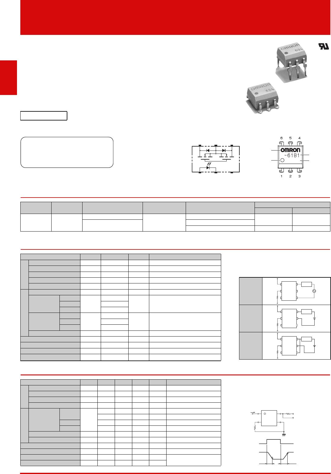
Terminal Arrangement /Internal Connections
List of Models
* The AC peak and DC value are given for the load voltage.
Absolute Maximum Ratings (Ta = 25°C)
Electrical Characteristics (Ta = 25°C)
RoHS compliant
Note: The actual product is marked differently from the
image shown here.
Test & Measurement equipment
Security equipment
Amusement equipment
6 54
13
2
OMRON logo
Pin 1 mark
Model
name
LOT.NO.
932
Note: The actual product is marked differently from the image shown here.
Package type Contact form Terminals
Load voltage
(peak value) *
Model
Minimum package quantity
Number per tube
Number per tape and reel
DIP6
1a
(SPST-NO)
PCB Terminals
350 V
G3VM-351B
50 -
Surface-mounting Terminals
G3VM-351E
G3VM-351E (TR) -1,500
Item Symbol Rating Unit Measurement conditions Note: 1.
The dielectric strength between the input and output was
checked by applying voltage between all pins as a group on
the LED side and all pins as a group on the light-receiving side.
Input
LED forward current IF 50 mA
Repetitive peak LED forward current
IFP 1 A 100 µs pulses, 100 pps
LED forward current reduction rate
IF/°C 0.5 mA/°C Ta 25°C
LED reverse voltage VR 5 V
Connection temperature
TJ 125 °C
Output
Load voltage (AC peak/DC)
VOFF 350 V
Continuous
load current
Connection A
IO
120
mA
Connection A: AC peak/DC
Connection B and C: DC
Connection B
120
Connection C
240
ON current
reduction
rate
Connection A
IO/°C
1.2
mA/°C Ta 25°C
Connection B
1.2
Connection C
2.4
Connection temperature
TJ 125 °C
Dielectric strength between I /O (See note 1.)
VI-O 2500 Vrms AC for 1 min
Ambient operating temperature
Ta 40 to +85 °C With no icing or condensation
Ambient storage temperature
Tstg 55 to +125 °C With no icing or condensation
Soldering temperature -260 °C 10 s
Item Symbol
Minimum
Typical
Maximum
Unit Measurement conditions
Input
LED forward voltage VF 1.0 1.15 1.3 V IF = 10 mA
Note: 2. Turn-ON and Turn-OFF Times
Reverse current IR - - 10 µA VR = 5 V
Capacity between terminals
CT - 30 - pF V = 0, f = 1 MHz
Trigger LED forward current
IFT -13mA IO = 120 mA
Output
Maximum
resistance with
output ON
Connection A
RON
-2535 IF = 5 mA, IO = 120 mA, t<1 s
-3550 I
F = 5 mA, IO = 120 mA
Connection B
-2840 IF = 5 mA, IO = 120 mA
Connection C
-1420 IF = 5 mA, IO = 240 mA
Current leakage when the relay is open
ILEAK --1.0µA VOFF = 350 V
Capacity between terminals
COFF - 30 - pF V = 0, f = 1 MHz
Capacity between I/O terminals
CI-O - 0.8 - pF f = 1 MHz, VS = 0 V
Insulation resistance between I/O terminals
RI-O 1000 - - M
V
I-O
= 500 VDC, R
O
H
60%
Turn-ON time tON -0.31.0ms
I
F = 5 mA, RL = 200 ,
V
DD = 20 V(See note 2.)
Turn-OFF time tOFF -0.11.0ms
Connection Diagram
Connection
A
Connection
B
Connection
C
Load
or AC
DC
1
2
3
6
5
4
1
2
3
6
5
4
DC
Load
Load
DC
1
2
3
6
5
4
VOUT
IF
tON tOFF
10%
90%
IF
1
2
6
4
RL
VDD
VOUT
2
G3VM-351B/E MOS FET Relays
Recommended Operating Conditions
Use the G3VM under the following conditions so that the Relay will operate properly.
Engineering Data
Safety Precautions
Refer to "Common Precautions" for all G3VM models.
Item Symbol Minimum Typical Maximum Unit
Load voltage (AC peak/DC) VDD --280V
Operating LED forward current
IF 5 10 25 mA
Continuous load current (AC peak/DC)
IO --100mA
Ambient operating temperature
Ta 20 - 65 °C
LED forward current vs. Ambient
temperature
Continuous load current vs. Ambient
temperature
LED forward current vs. LED forward
voltage
Continuous load current vs. On-state
voltage
On-state resistance vs. Ambient
temperature
Trigger LED forward current vs.
Ambient temperature
Turn ON, Turn OFF time vs. LED
forward current
Turn ON, Turn OFF time vs. Ambient
temperature
Current leakage vs. Ambient
temperature
I
F
- Ta
Ambient temperature Ta (°C)
LED forward current I
F
(mA)
-20
120100 80 60 40 020
0
60
20
40
80
100
I
O
- Ta
Ambient temperature Ta (°C)
Continuous load current I
O
(mA)
-20
120100 80 60 40 020
0
280
240
200
160
120
80
40
Connection C
Connection A and B
I
F
- V
F
LED forward voltage V
F
(V)
LED forward current I
F
(mA)
1.4
0.6
0.8 1 1.2 1.6 1.8
100
30
10
3
1
0.3
0.1
Ta = 25°C
I
O
- V
ON
On-state voltage V
ON
(V)
Continuous load current I
O
(mA)
-200
-100
0
100
200
Ta = 25°C
I
F = 5mA
Connection A
-4
4
-3 -2 -1 0 1 2 3
R
ON
- Ta
On-state resistance R
ON
()
Ambient temperature Ta (°C)
-20
10080 60 40 020
30
0
10
20
40
50
IO = 120mA
I
F = 5mA
t < 1s
Connection A
I
FT
- Ta
Ambient temperature Ta (°C)
Trigger LED forward current I
FT
(mA)
-20
10080 60 40 020
3
0
1
2
4
5
IO = 120mA
t < 1s
t
ON
, t
OFF
- I
F
LED forward current I
F
(mA)
101
3 30 100 300
10
30
100
300
1000
3000
Ta = 25ºC
V
DD = 20V
R
L = 200
tOFF
tON
Turn ON, Turn OFF time t
ON
, t
OFF
(µs)
t
ON
, t
OFF
- Ta
Ambient temperature Ta (°C)
-20
10080 60 40 020
10
3000
1000
300
100
30
VDD = 20V
R
L = 200
I
F = 5mA
tON
tOFF
Turn ON, Turn OFF time t
ON
, t
OFF
(µs)
I
LEAK
- Ta
Current leakage I
LEAK
(nA)
Ambient temperature Ta (°C)
-20
100 80 60 40 020
10
0.1
30
1
3
0.3
VOFF = 350V
Appearance/Dimensions DIP6 type
Appearance
Dimensions (Unit:mm)
Note: The actual product is marked differently from the
image shown here.
PCB Dimensions (BOTTOM VIEW)
Actual Mounting Pad Dimensions
(Recommended Value, TOP VIEW)
DIP6
DIP (Dual Inline Package)
OMRON logo
Pin 1 mark
Model name
LOT.NO.
932
Note: The actual product is marked differently from the image shown here.
7.12
±0.25
6.4
±0.25
2.54
±0.25
1.2
±0.15
0.5
±0.1
0.8
±0.25
7.62
±0.25
7.85 to 8.80
3.65
0.25
2.5 min.
+0.15
−0.25
+0.1
−0.05
PCB Terminals
Weight: 0.4 g
7.12±0.25
6.4±0.25
2.54±0.25
1.2±0.15
7.62±0.25
10.0 max.
1.0 min.
3.65 4.0
+0.15
−0.25
+0.25
−0.2
1.0 min.
Surface-mounting Terminals
Weight: 0.4 g
Six, 0.8-dia. holes
2.54
2.54
(0.61)
(0.61)
(1.52)(1.52)
8.3 to 8.8
2.54 2.54
1.5
1.3
Application examples provided in this document are for reference only. In actual applications, confirm equipment functions and safety before using the product.
Consult your OMRON representative before using the product under conditions which are not described in the manual or applying the product to nuclear control systems, railroad
systems, aviation systems, vehicles, combustion systems, medical equipment, amusement machines, safety equipment, and other systems or equipment that may have a serious
influence on lives and property if used improperly. Make sure that the ratings and performance characteristics of the product provide a margin of safety for the system or
equipment, and be sure to provide the system or equipment with double safety mechanisms.
Cat. No. K147-E1-01
0412(0412)(O)
Note: Do not use this document to operate the Unit.
OMRON Corporation
ELECTRONIC AND MECHANICAL COMPONENTS COMPANY
Contact: www.omron.com/ecb

G3VM-351E

Mfr. #:
Manufacturer:
Description:
Solid State Relays - PCB Mount 350V, SPST-NO, SMD6 SMT 120mA 35ohm 30pF
Lifecycle:
New from this manufacturer.
Delivery:
DHL FedEx Ups TNT EMS
Payment:
T/T Paypal Visa MoneyGram Western Union

Products related to this Datasheet