Product specifications in this catalog are subject to change without notice.Request our product specifications before purchase and/or use. Please use our products based on the information contained in this catalog and product specifications.
Low ESR, 105℃
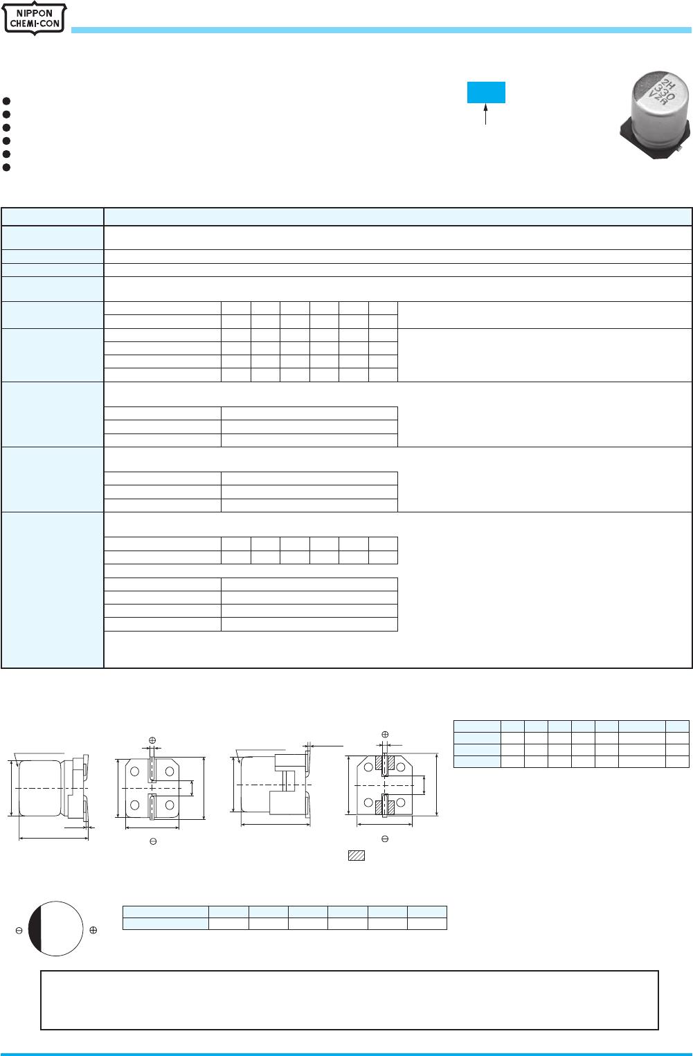
AIchip
TM
-MZRSeries
・
Downsizing and Lower ESR, 2,000hours at 105
℃
・
Rated voltage range : 6.3 to 50V, Nominal capacitance range : 100 to 2,200μF
・
Solvent resistant type(see PRECAUTIONS AND GUIDELINES)
・
Vibration resistance structure
・
RoHS2 Compliant
・
AEC-Q200 compliant : Please contact Chemi-Con for more details, test data, information.
◆
SPECIFICATIONS
Items Characteristics
Category
Temperature Range
-55 to +105
℃
Rated Voltage Range
6.3 to 50V
dc
Capacitance Tolerance
±
20% (M) (at 20
℃
, 120Hz)
Leakage Current
I=0.01CV or 3μA, whichever is greater.
Where, I : Max. leakage current (μA), C : Nominal capacitance (μF), V : Rated voltage (V) (at 20
℃
after 2 minutes)
Dissipation Factor
(tan
δ
)
Rated voltage (V
dc
) 6.3V 10V 16V 25V 35V 50V (at 20
℃
, 120Hz)
tan
δ
(Max.) 0.26 0.19 0.16 0.14 0.12 0.10
Low Temperature
Characteristics
(Max. Impedance Ratio)
Rated voltage (V
dc
) 6.3V 10V 16V 25V 35V 50V (at 120Hz)
Z(-25
℃
)/Z(+20
℃
) 2 2 2 2 2 2
Z(-40
℃
)/Z(+20
℃
) 3 3 3 3 3 3
Z(-55
℃
)/Z(+20
℃
) 4 4 4 3 3 3
Endurance
The following specifications shall be satisfied when the capacitors are restored to 20
℃
after the rated voltage is applied for 2,000 hours
at 105
℃
.
Capacitance change
≦±
30% of the initial value
D.F. (tan
δ
)
≦
200% of the initial specified value
Leakage current
≦
The initial specified value
Shelf Life
The following specifications shall be satisfied when the capacitors are restored to 20
℃
after exposing them for 1,000 hours at 105
℃
without
voltage applied. Before the measurement, the capacitor shall be preconditioned by applying voltage according to Item 4.1 of JIS C 5101-4.
Capacitance change
≦±
30% of the initial value
D.F. (tan
δ
)
≦
200% of the initial specified value
Leakage current
≦
The initial specified value
Surge Voltage Test
The capacitors shall be subjected to 1,000 cycles each consisting of charging with the specified surge voltage for 30
±
5 seconds through
a protective resistor (as required for RC=0.1
±
0.05sec) and open-circuiting for 5.5 minutes at a room temperature of 15 to 35
℃
.
Rated voltage (V
dc
) 6.3V 10V 16V 25V 35V 50V
Surge voltage (V
dc
) 7.2V 12V 18V 29V 40V 58V
Appearance No significant damage
Capacitance change
≦±
20% of the initial value
D.F. (tan
δ
)
≦
200% of the initial specified value
Leakage current
≦
The initial specified value
(Caution)
Surge Voltage Test intends to evaluate capacitors in durability of an exceptional excessive voltage under specific conditions.It does
not imply long-term use at all.
◆
DIMENSIONS [mm]
L±0.3 (Note)
0.3max.
A±0.2
W
C±0.2
B±0.2
P
Note : L±0.5 for HA0 and JA0
φD±0.5
B±0.2
L±0.5
0.3max.
A±0.2
W
C±0.2
P
● Size code : F80 to JA0
●
Terminal Code : G(Vibration resistant structure)
● Size code : HA0 and JA0
●
Vent for JA0
Vent for JA0
◆
MARKING
3Q
330
V
ZR
Rated voltage (Vdc)
Symbol
6.3 10 16 25 35
j A C E V
50
H
Applying voltage over the rated voltages causes the capacitors to have short lifetime.
Besides, applying voltage over the specified surge voltages may cause to have short circuit failure. A protection
circuit should be used if applied voltage will exceed the rated voltages.
Downsized
MZR
MZJ P4-14
Size code
F80
HA0
JA0
D
6.3
8
10
L
7.7
10.0
10.0
A
6.6
8.3
10.3
B
6.6
8.3
10.3
C
7.2
9.0
11.0
W
0.5 to 0.8
0.7 to 1.1
0.7 to 1.1
P
1.9
3.1
4.5
4-12
CAT. No. E1001R
SURFACE MOUNT ALUMINUM ELECTROLYTIC CAPACITORS
