K–7
Dimensions are shown: Inch (mm)
Specifications and dimensions subject to change
www.ck-components.com
A Series
1-4 Pole Rotary Switches
FUNCTION
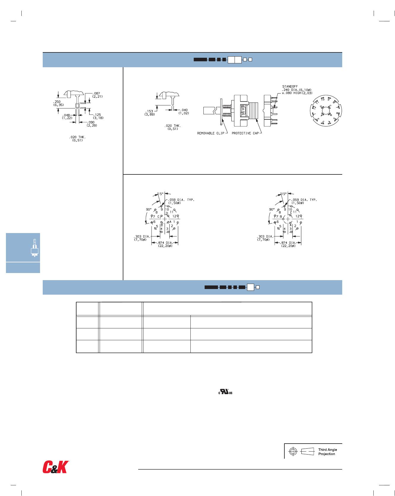
AVAILABLE HARDWARE
(FIG. 1)
(FIG. 2) (FIG. 3)
REMOV
ABLE CLIP
LOCATING
TA B
STANDOFF
K
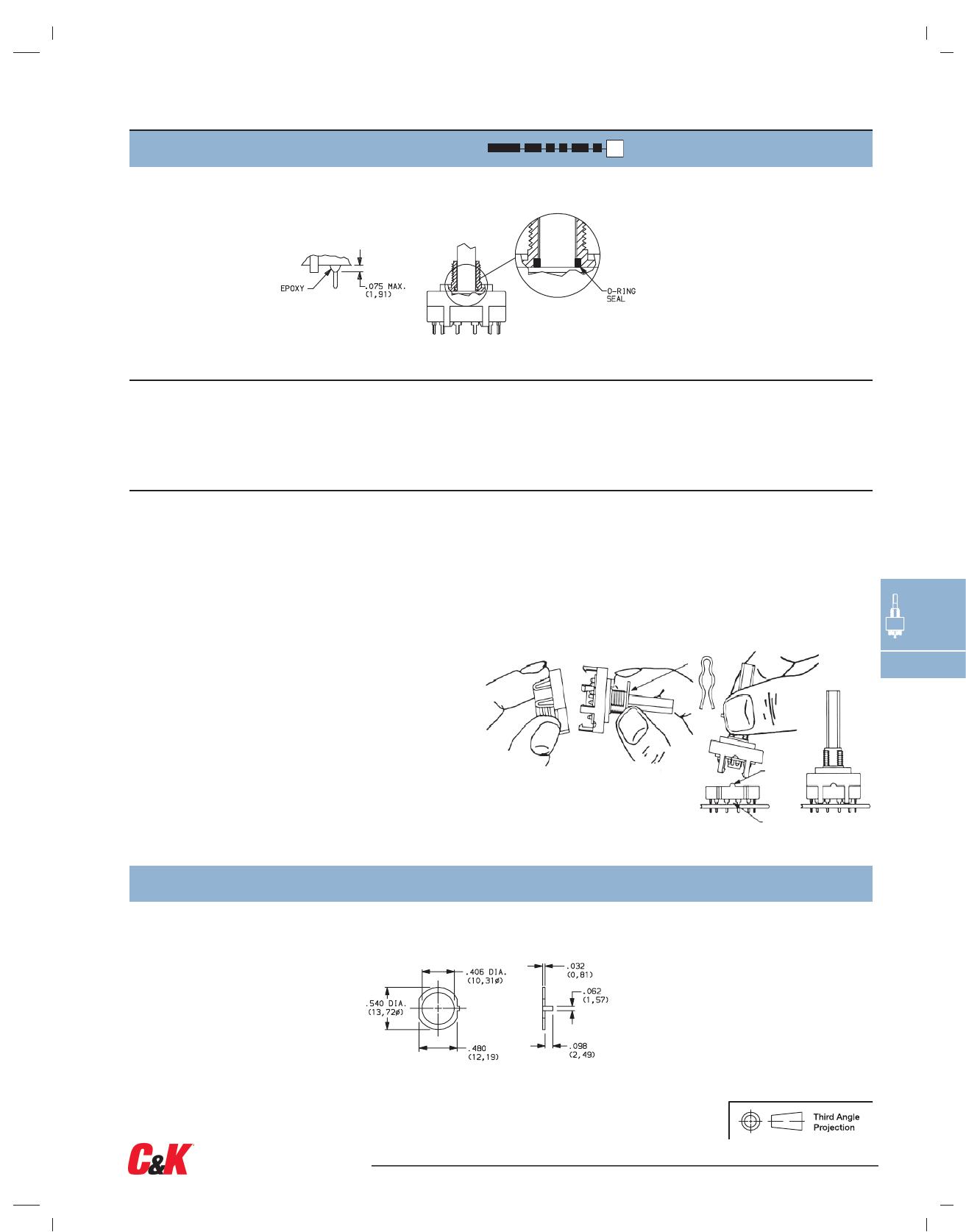
EPOXY & SPLASHPROOF BUSHING SEAL
F
SPLASHPROOF BUSHING SEAL
NONE
NO SEAL
E
EPOXY SEAL
Stop ring
P
ART NO.
767B00201
Material: Brass
Finish: Nickel plated
Setting Stops on A112 and A125 Models
The number of switch positions is adjustable on A112
and A125 models only by means of a stop ring provided
with each switch. The number of positions is pre-set on
all other models and the stop ring is factory installed.
Soldering
1. Insert switch base only into PC board.
2. Do not bend terminals.
3. Wave soldering recommended at
500F solder temperature.
4. Hand solder at 500F, 10 sec.
max./terminal.
Switch Assembly
1. Hold housing/shaft assembly by housing. Remove
protective cap by squeezing tabs and discard. (FIG. 1)
2.
Do not push on switch shaft. Detent mechanism will
come apart.
3. While holding switch housing, align locating tab on
base with notch on housing and engage 4 housing
latches in slots on base. (FIG. 2)
4. Push firmly on housing until latches snap in place.
5. Remove clip from shaft and discard. Assembly is
complete. (FIG. 3)
Cleaning
1. Flux clean using vapor degreaser and forced
rinse or triple bath method.
2. Do not allow switch base to ‘trap’ fluids.
3. Freon TMC, TF or Methylene Chloride give
excellent results.
To set stops: Turn shaft fully counter-clockwise and
insert stop ring tab in desired hole. Install lockwasher
and nut to retain stop ring for both PC and panel
mounting. Switch without stop ring has 12 positions.
Soldering, Cleaning and Assembly Instructions for ‘MC’ Termination Option