SM15T Characteristics
Doc ID 3080 Rev 6 5/10
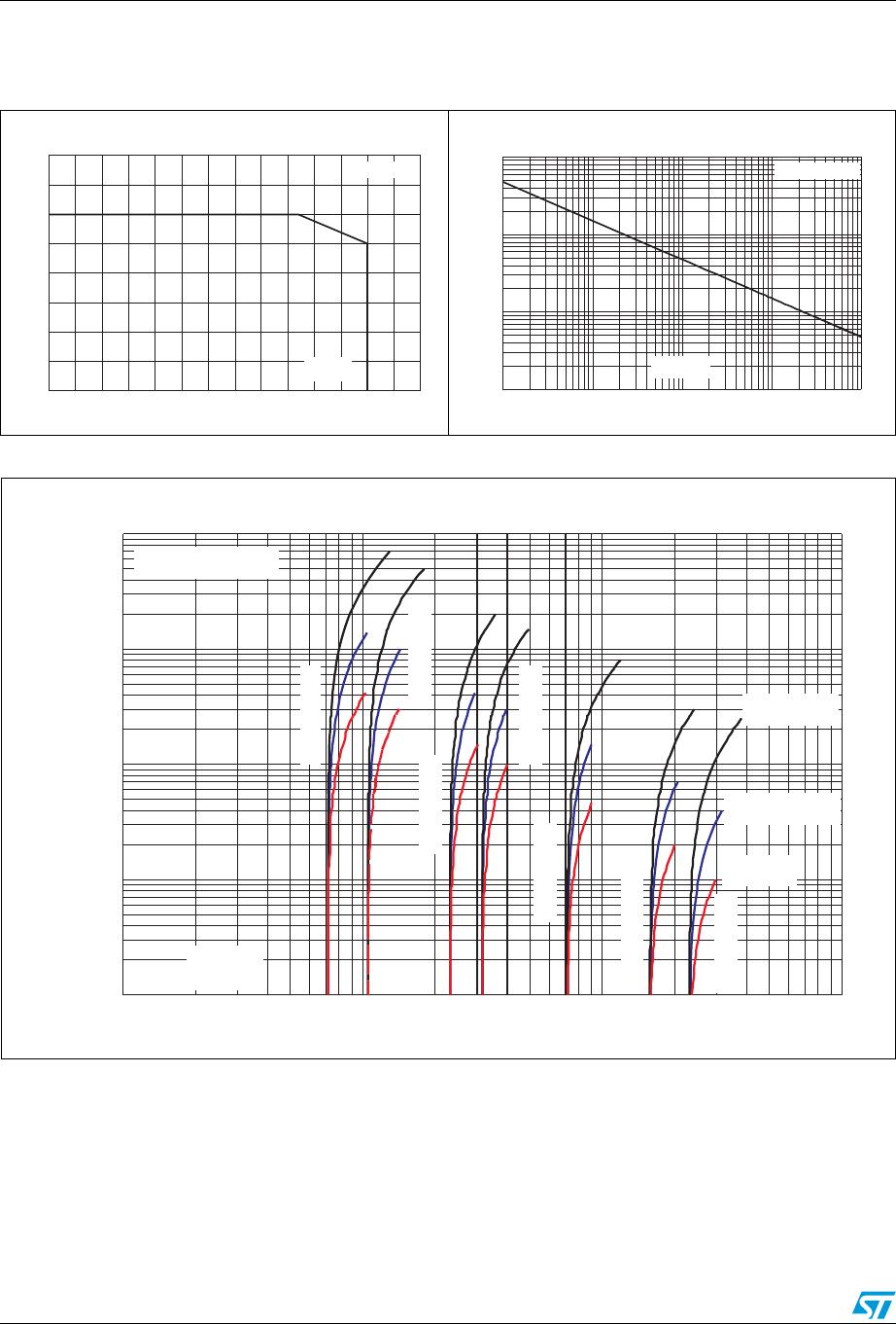
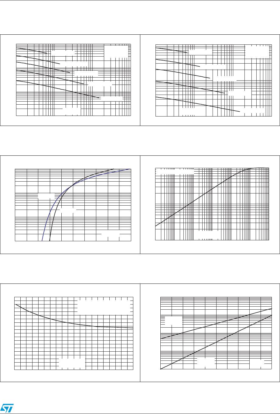
Figure 6. Capacitance versus reverse applied
voltage (typical values, SM15TxxA)
Figure 7. Capacitance versus reverse applied
voltage (typical values,
SM15TxxCA)
C (nF)
0.01
0.10
1.00
10.00
1 10 100 1000
F=1 MHz
V
osc
=30 mV
RMS
T
j
=25 °C
SM15T6V8A
SM15T15A
SM15T30A
SM15T68A
SM15T200A
V (V)
R
C (nF)
0.1
1.0
10.0
1 10 100 1000
F=1 MHz
V
osc
=30 mV
RMS
T
j
=25 °C
SM15T6V8CA
SM15T15CA
SM15T30CA
SM15T68CA
SM15T200CA
V (V)
R
Figure 8. Peak forward voltage drop versus
forward current (typical values)
Figure 9. Relative variation of thermal
impedance junction to ambient
versus pulse duration
I (A)
FM
0.1
1.0
10.0
100.0
0.0 0.5 1.0 1.5 2.0 2.5
T
j
=25 °C
T
j
=125 °C
V (V)
FM
0.01
0.10
1.00
1.0E-03 1.0E-02 1.0E-01 1.0E+00 1.0E+01 1.0E+02 1.0E+03
Z
th(j-a)
/R
th(j-a)
Recommended pad layout
t
P
(s)
Figure 10. Thermal resistance junction to
ambient versus copper surface
under each lead
Figure 11. Leakage current versus junction
temperature (typical values)
R
th(j-a)
(°C/ W)
0
10
20
30
40
50
60
70
80
90
100
0.0 0.5 1.0 1.5 2.0 2.5 3.0 3.5 4.0 4.5 5.0
printed circuit board FR4,
copper thickness = 35 µm
S
Cu
(cm²)
I
R
(n A )
1.0E+00
1.0E+01
1.0E+02
1.0E+03
1.0E+04
25 50 75 100 125 150
V
R
=V
RM
V
RM
≥ 10 V
V
R
=V
RM
V
RM
< 10 V
T (°C)
j