USA 858 674 8100
••
Germany 49 7032 7806 0
••
Singapore 65 6287 8998
••
Shanghai
86 21 54643211 / 2
••
China 86 755 33966678
••
Taiwan 886 3 4641811
www.pulseeng.com
43
SPM2007 (11/07)
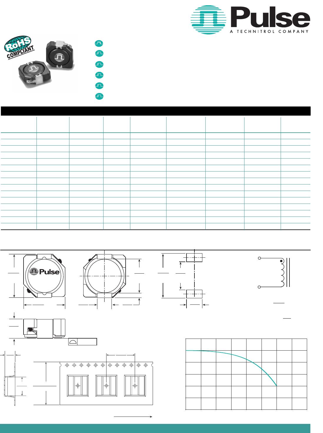
SMT POWER INDUCTORS
Shielded Drum Core Series
Notes from Tables (pages 27 - 42)
1. Unless otherwise specified, all testing is made at
100kHz, 0.1VAC.
2.
Optional Tape & Reel packaging can be ordered by
adding a "T" suffix to the part number (i.e. P1166.102NL
becomes P1166.102NLT). Pulse complies with industry
standard Tape and Tape & Reel specification EIA481.
3. The "NL" suffix indicates an RoHS-compliant part
number. Non-NL suffixed parts are not necessarily
RoHS compliant, but are electrically and mechanically
equivalent to NL versions. If a part number does not
have the "NL" suffix, but an RoHS compliant version is
required, please contact Pulse for availability.
4. Temperature of the component (ambient plus
temperature rise) must be within specified operating
temperature range.
5. The rated current (Irated) as listed is either the satura-
tion current or the heating current depending on which
value is lower.
6. The saturation current, Isat, is the current at which
the component inductance drops by the indicated
percentage (typical) at an ambient temperature of
25°C. This current is determined by placing the
component in the specified ambient environment and
applying a short duration pulse current (to eliminate
self-heating effects) to the component.
7. The heating current, Idc, is the DC current required
to raise the component temperature by the indicated
delta (approximately). The heating current is
determined by mounting the component on a
typical PCB and applying current for 30 minutes. The
temperature is measured by placing the thermocouple
on top of the unit under test.
8. In high volt*time (Et) or ripple current applications, addi-
tional heating in the component can occur due to core
losses in the inductor which may necessitate derating
the current in order to limit the temperature rise of the
component. In order to determine the approximate total
loss (or temperature rise) for a given application, both
copper losses and core losses should be taken into
account.
Estimated Temperature Rise:
Trise = [Total loss (mW) / K0]
.833
(
o
C )
Total loss = Copper loss + Core loss (mW)
Copper loss = I
RMS
2
x DCR (Typical) (mW)
Irms = [I
DC
2
+ ΔI
2
/12]
1/2
(A)
Core loss = K1 x f (kHz)
1.23
x Bac(Ga)
2.38
(mW)
Bac (peak to peak flux density) = K2 x ΔI (Ga)
[= K2/L(µH) x Et(V-µSec) (Ga)]
where f varies between 25kHz and 1MHz, and Bac is
less than 2500 Gauss.
K2 is a core size and winding dependant value and
is given for each p/n in the proceeding datasheets.
K0 & K1 are platform and material dependant constants
and are given in the table below for each platform.
PG0085/86 2.3 5.29E-10
PG0087 5.8 15.2E-10
PG0040/41 0.8 2.80E-10
P1174 0.8 6.47E-10
PF0601 4.6 14.0E-10
PF0464 3.6 24.7E-10
PF0465 3.6 33.4E-10
P1166 1.9 29.6E-10
P1167 2.1 42.2E-10
PF0560NL 5.5 136E-10
P1168/69 4.8 184E-10
P1170/71 4.3 201E-10
P1172/73 5.6 411E-10
PF0552NL 8.3 201E-10
PF0553NL 7.1 411E-10
Part No.
Trise Factor Core Loss Factor
(K0 ) (K1)
Take note that the component's temperature rise varies depending on the system condition. It is suggested that the
component be tested at the system level, to verify the temperature rise of the component during system operation.