LTC4371
16
4371f
For more information www.linear.com/LTC4371
applicaTions inForMaTion
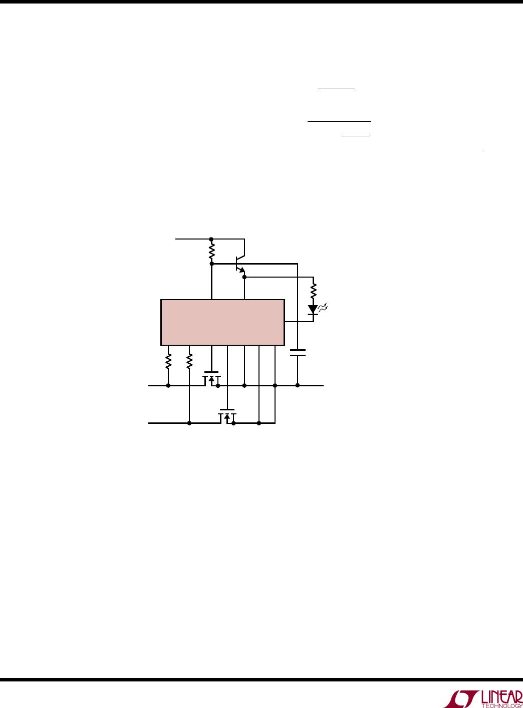
Figure18. –36V to –72V/25A Ideal Diode-OR
As a second design example, consider modifying the
circuit of Figure17 to handle 300V transients and to drive
a red LED, which illuminates when a fault is present (see
Figure18). R
DA
and R
DB
are sized to handle transients to
300V, so no change in their value is necessary. Modifica-
tions are necessary to drive the red LED.
A PZT
A42
, a 300V NPN with a minimum β = 20 is chosen
to supply both the LED and the V
DD
pin. With a maxi-
mum I
DD
of 9.5mA (LTC4371) + 1mA (LED) = 10.5mA,
Equation4 gives:
I
BASE
=
20
= 525µA (13)
R
Z
<
36V –11.8V
50uA+
10mA
= 44k
The nearest lower 5% value is 43k.
To produce 1mA LED current with variations in the circuit,
R1 is chosen to be 8.2k.
4371 F18
LTC4371
DA DB GA GB SA
V
Z
V
DD
SB V
SS
R
DA
20k
R
DB
20k
M1
IPT020N10N3
M2
IPT020N10N3
V
A
–36V TO
–72V
V
B
–36V TO
–72V
V
OUT
25A LOAD
D1
RED LED = MOSFET BAD
R
Z
43k
R1
8.2k
RTN
FAULTB
Q1
PZTA42
C1
0.1μF