www.vishay.com For technical questions, contact: optocoupleranswers@vishay.com
Document Number: 83652
4 Rev. 1.6, 04-Mar-11
ILD615, ILQ615
Vishay Semiconductors
Optocoupler, Phototransistor Output
(Dual, Quad Channel)
Note
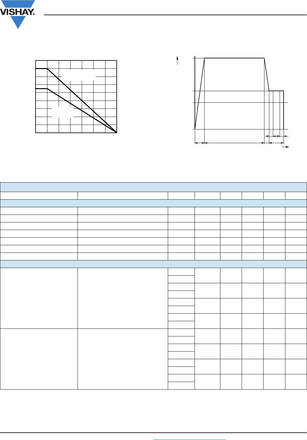
• According to DIN EN 60747-5-2 (see figure 2). This optocoupler is suitable for safe electrical isolation only within the safety ratings.
Compliance with the safety ratings shall be ensured by means of suitable protective circuits.
CURRENT TRANSFER RATIO (T
amb
= 25 °C, unless otherwise specified)
PARAMETER TEST CONDITION PART SYMBOL MIN. TYP. MAX. UNIT
Current transfer ratio
(collector emitter saturated)
I
F
= 10 mA, V
CE
= 0.4 V
ILD615-1
CTR
CEsat
25 %
ILQ615-1
ILD615-2
CTR
CEsat
40 %
ILQ615-2
ILD615-3
CTR
CEsat
60 %
ILQ615-3
ILD615-4
CTR
CEsat
100 %
ILQ615-4
Current transfer ratio
(collector emitter)
I
F
= 1 mA, V
CE
= 5 V
ILD615-1
CTR
CE
13 30 %
ILQ615-1
ILD615-2
CTR
CE
22 45 %
ILQ615-2
ILD615-3
CTR
CE
34 70 %
ILQ615-3
ILD615-4
CTR
CE
56 90 %
ILQ615-4
I
F
= 10 mA, V
CE
= 5 V
ILD615-1
CTR
CE
40 60 80 %
ILQ615-1
ILD615-2
CTR
CE
63 80 125 %
ILQ615-2
ILD615-3
CTR
CE
100 150 200 %
ILQ615-3
ILD615-4
CTR
CE
160 200 320 %
ILQ615-4
SAFETY AND INSULATION RATED PARAMETERS
PARAMETER TEST CONDITION SYMBOL MIN. TYP. MAX. UNIT
Partial discharge test voltage -
routine test
100 %, t
test
= 1 s V
pd
1.669 kV
Partial discharge test voltage -
lot test (sample test)
t
Tr
= 60 s, t
test
= 10 s,
(see figure 2)
V
IOTM
10 kV
V
pd
1.424 kV
Insulation resistance
V
IO
= 500 V R
IO
10
12
V
IO
= 500 V, T
amb
= 100 °C R
IO
10
11
V
IO
= 500 V, T
amb
175 °C
(construction test only)
R
IO
10
9
Forward current I
SI
275 mA
Power dissipation P
SO
400 mW
Rated impulse voltage V
IOTM
10 kV
Safety temperature T
SI
175 °C