1-866-9-OHMITE • Int’l 1-847-258-0300 • Fax 1-847-574-7522 • www.ohmite.com • info@ohmite.com
34
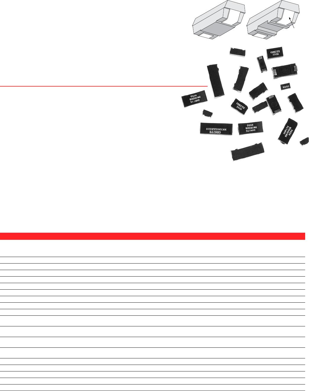
Surface Mount Power
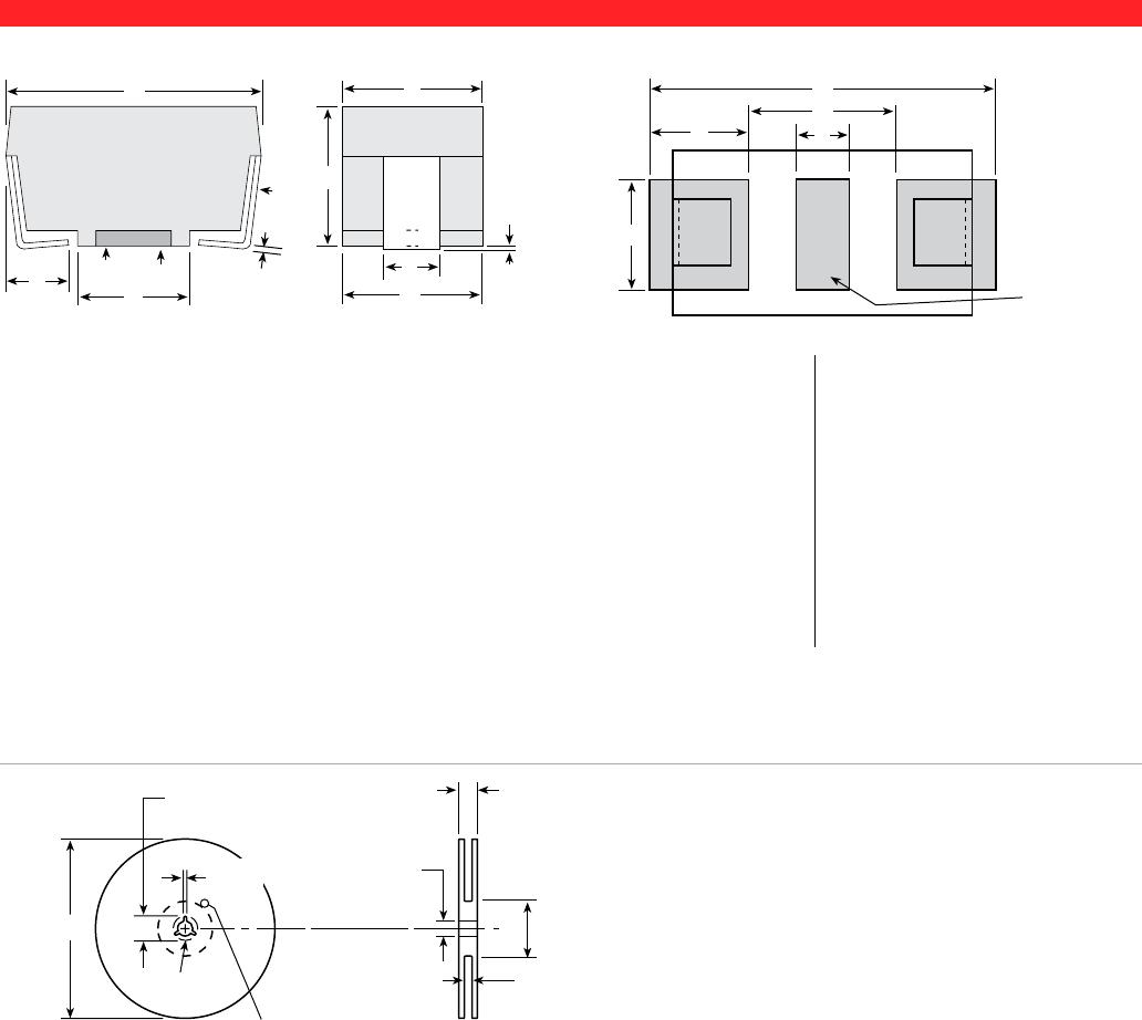
Package Outline Dimensions PC Board Land Pattern
Packages A B C D G I J L M N O P
BA (in.) 0.246±.020 0.136±.005 0.133 REF 0.110±.010 0.047 ±0.020 0.054±.012 0.136±.005 0.150 0.346 0.098 0.126 0.050
(mm) 6.248±.508 3.454±.127 3.378 REF 2.794±.254 1.194 ±0.508 1.372±.305 3.454±.127 3.81 8.79 2.49 3.20 1.27
CA (in.) 0.394±.020 0.159±.005 0.156 REF 0.220±.010 0.062 Nom. 0.078±.012 0.159±.005 0.256 0.524 0.134 0.126 0.060
(mm) 10.008±.508 4.039±.127 3.962 REF 5.588±.254 1.575 Nom. 1.981±.305 4.038±.127 6.50 13.31 3.40 3.20 1.52
CB (in.) 0.407±.020 0.226±.005 0.222 REF 0.260±.010 0.062 Nom. 0.084±.012 0.222±.005 0.276 0.537 0.131 0.126 0.093
(mm) 10.338±.508 5.74±.127 5.639 REF 6.604±.254 1.575 Nom. 2.134±.305 5.639±.127 7.01 13.64 3.33 3.20 2.36
DA (in.) 0.455±.020 0.240±.005 0.236 REF 0.260±.010 0.062 Nom. 0.143±.012 0.226±.005 0.317 0.585 0.134 0.155 0.093
(mm) 11.557±.508 6.096±.127 5.994 REF 6.604±.254 1.575 Nom. 3.632±.305 5.740±.127 8.05 14.86 3.40 3.94 2.36
DB (in.) 0.625±.020 0.273±.005 0.268 REF 0.417±.010 0.062 Nom. 0.143±.012 0.226±.005 0.474 0.742 0.134 0.155 0.093
(mm) 15.875±.508 6.934±.127 6.807 REF 10.592±.254 1.575 Nom. 3.632±.305 5.740±.127 12.040 18.85 3.40 3.94 2.36
EA (in.) 0.811±.020 0.273±.005 0.268 REF 0.572±.010 0.093 Nom. 0.143±.012 0.273±.005 0.611 1.000 0.195 0.155 0.093
(mm) 20.599±.508 6.934±.127 6.807 REF 14.529±.254 2.362 Nom. 3.632±.305 6.934±.127 15.52 25.4 4.95 3.94 2.36
BB (in.) 0.202±.010 0.10±.010 0.095 REF 0.079±.010 0.050 Nom. 0.065±.012 0.135±.005 0.078 0.328 0.125 0.126 0.026
(mm) 5.140±.508 2.54±.127 2.41 REF 2.00±.254 1.280 Nom. 1.640±.305 3.420±.127 1.98 8.33 3.18 3.20 0.66
J
I
C
B
K
=0.006 Ref.
D
A
E
G
H
Note 1
F
=0.005 ±.001
Note 2
L
O
M
P
N
Recommended
for glue dot
application
Note 1: Packages BA and CA are only available with a pedestal base. Packages CB and DA are available in either pedestal or recessed base. Packages DB and EA
are only available in a recessed base.
Note 2: Test point is .020 above PCB.
Note 3: Tape and reel dimensions per EIA 481 A except “EA” size which is 12 mm component pitch versus 16mm pitch.
Size A nom. B C max. Quantity
12mm 13” 0.488" +0.078, –0.00 0.724" 2000 pcs. BA or
12.4mm +2.0, –0.0 18.4mm 2500 pcs. BB
16mm 13” 0.646" +0.078, –0.00 0.882" 1500 pcs. CA or
16.4mm +2.0, –0.0 22.4mm 1000 pcs. CB
24mm 13” 0.961" +0.078, –0.00 1.196" 1000 pcs. DA or DB
24.4mm +2.0, –0.0 30.4mm
32mm 13” 1.276" +0.078, –0.00 1.52" 750 pcs. EA
32.4mm +2.0, –0.0 38.4mm
Reel Dimensions
All reels are compatible with major pick-and-place machines
and made in accordance with EIA 481 A (except EA size,
which is 12mm component pitch versus 16mm pitch).
A
0.795*
20.2
min.
0.512 ±.008
13.0
±
.200
C
B
1.973
50
min.
0.059*
1.5
min.
Full
Radius
Tape Start Slot
Measured
at Hub
0.098 /
2.5
min. width
0.394 /
10
min. depth
Land pattern dimensions are for reference only
DIMENSIONS
(in./mm)
(continued)