2
Technical Data 4451
Effective March 2015
FPT705 Family
Dual conductor, high current power inductors
www.eaton.com/elx
Recommended Pad Layout Schematic
7.8
±0.5
5.35
max
7.2
7.0
±0.3
1.25
±0.1
0.1
typ
0.60
±0.20
1.5
±0.25
3.7
1.7
1.0
7.9
1.65
0.40
Resist area
Product Specifications
Part Number
5
OCL
1
(nH) ±10%
I
rms
2
(amps)
I
sat
3
(amps)
DCR (mΩ)
@ 20°C
±0.15 mΩ
FPT705-170-R 170 (±12%) 13 31 0.65
FPT705-190-R 190 13 28 0.65
FPT705-200-R 200 13 25 0.65
FPT705-230-R 230 13 23 0.65
FPT705-270-R 270 13 19 0.65
FPT705-300-R 300 13 17 0.65
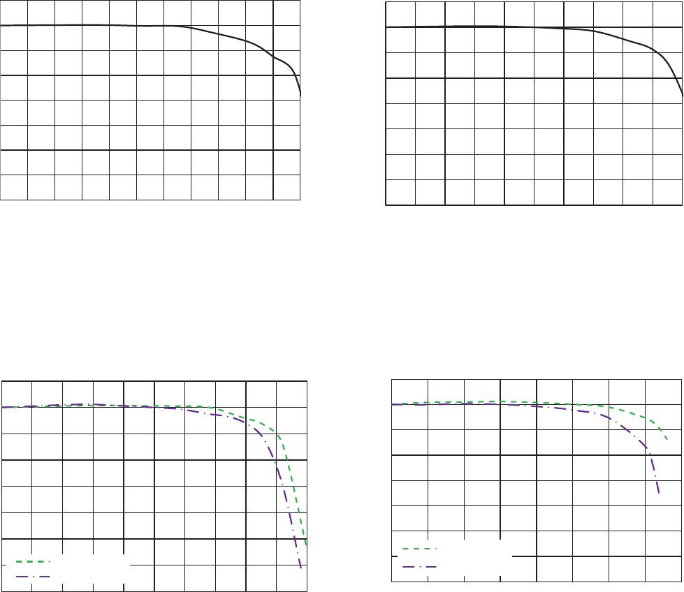
1. Open Circuit Inductance (OCL) Test Parameters: 1.0MHz, 0.1Vrms, 0.0Adc, 25°C
2. I
rms
: DC current for an approximate temperature rise of 40°C without core loss. Derating is necessary for AC currents.
PCB layout, trace thickness and width, air-flow, and proximity of other heat generating components will affect the
temperature rise. It is recommended that the temperature of the part not exceed 125°C under worst case operating
conditions verified in the end application.
3. I
sat
Peak current for approximately 2% rolloff @ +25°C
4. DCR tested from pins (1-2) and pins (4-3)
5. Part Number Definition: FPT705-xxx-R
FPT705 = Product code and size
xxx= Inductance value in nH,
-R suffix = RoHS compliant
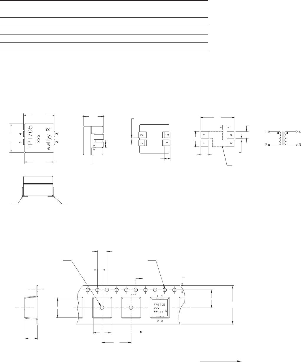
Dimensions (mm)
Packaging information (mm)
Supplied in tape and reel packaging, 1,000 parts per 13” diameter reel
Part marking: FPT705, xxx=inductance value in nH, wwllyy= date code R= revision level
Soldering surfaces to be coplanar within 0.10 millimeters
DCR is measured from point “a” to point “b”
Pins 2 and 4 are connected through the PCB trace
4.0
1.5 dia 1.5 dia
2.0
1.75
16.0
±0.3
7.5
8.2
5.55
12.0
7.4
Section A–A
A
A