MS4515DO
SENSOR SOLUTIONS
/// MS4515DO
ENVIRONMENTAL SPECIFICATIONS
Mil Spec 202F, Method 213B, Condition C, 3 Drops
Mil Spec 202F, Method 214A, Condition 1E, 1Hr Each Axis
100 Cycles over Storage Temperature, 30 minute dwell
>10Yrs, 70 ºC, 1.188 Million Pressure Cycles, 120%FS Pressure
PERFORMANCE SPECIFICATIONS
Supply Voltage
1
: 5.0V or 3.3 Vdc
Reference Temperature: 25°C (unless otherwise specified)
Output Pressure Resolution
Output Temperature Resolution
Non-Corrosive Dry Gases Compatible with Ceramic, Silicon,
Borosilicate Glass, RTV, Gold, Aluminum and Epoxy. See
“Wetted Material by Port Designation” chart below.
Notes
1. Proper operation requires an external capacitor placed as shown in Connection Diagram. Output is not ratiometric to supply voltage.
2. The maximum deviation from a best fit straight line (BFSL) fitted to the output measured over the pressure range at 25C. Includes all
errors due to pressure non linearity, hysteresis, and non repeatability.
3. Total pressure error band includes all accuracy errors, thermal errors over the compensated temperature range and span and offset
calibration tolerances. For ideal sensor output with respect to input pressure and temperature, reference Transfer Function charts below.
TEB values are valid only at the calibrated supply voltage.
4. The deviation from a best fit straight line (BFSL) fitted to the output measured over the compensated temperature range.
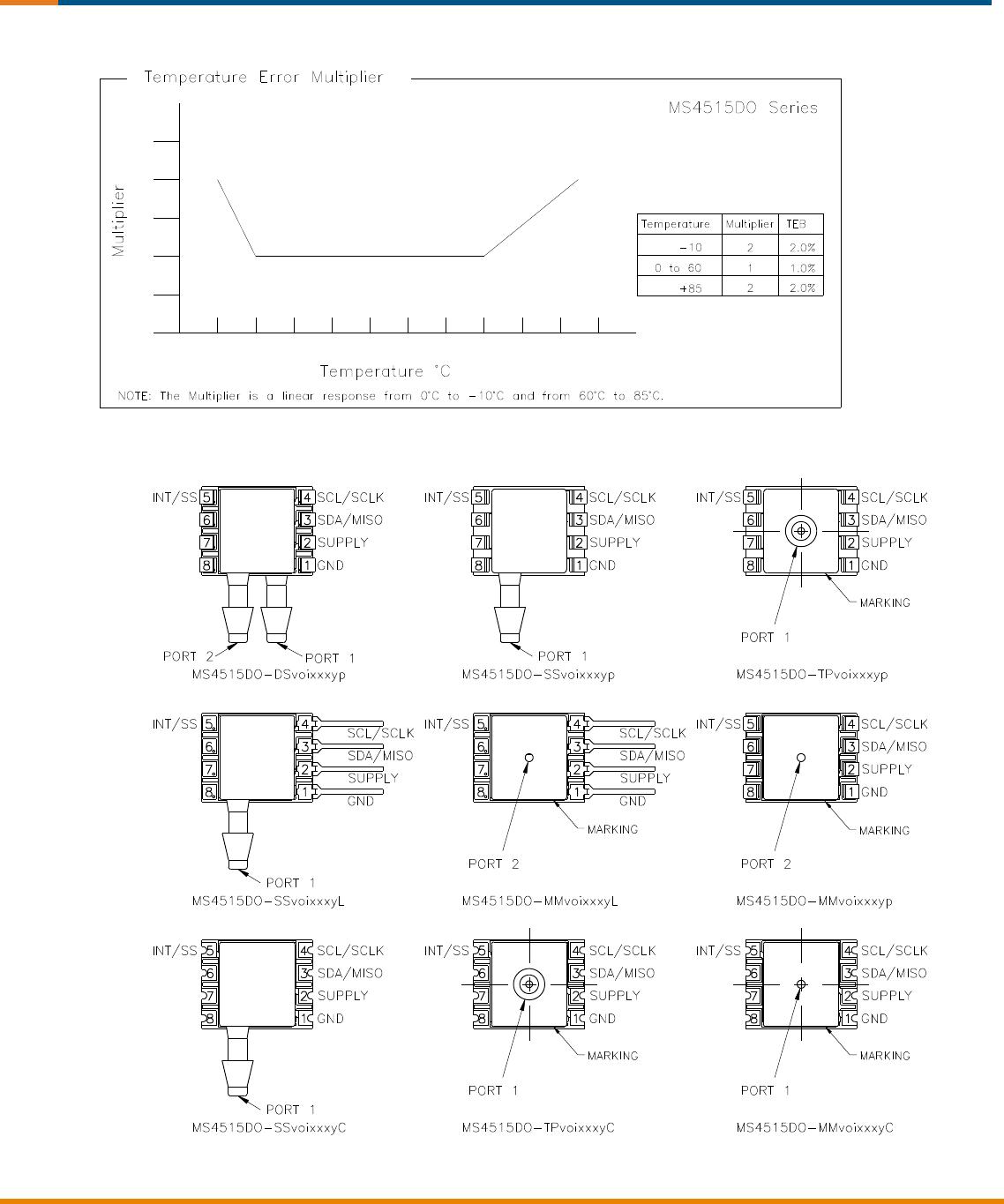
5. For errors beyond the compensated temperature range, see Extended Temperature Multiplier chart below.
6. Start time to data ready is the time to get valid data after POR (power on reset). The time to get subsequent valid data is then specified
by the update time specification.
7. This product can be configured for custom OEM requirements, contact factory for lower power consumption or higher accuracy.