80 Ohmite Mfg. Co. 1-866-9-OHMITE • Int’l 1-847-258-0300 • Fax 1-847-574-7522 • www.ohmite.com • info@ohmite.com
Ohmite Mfg. Co. 1600 Golf Rd., Rolling Meadows, IL 60008 • 1-866-9-OHMITE • Int’l 1-847-258-0300 • Fax 1-847-574-7522 • www.ohmite.com • info@ohmite.com 81
S T A N D A R D P A R T N U M B E R S F O R P O W E R T A P S W I T C H E S
Ohmite power Tap Switches
(high power rotary switches)
are constructed to provide
dependable, convenient
operation.
All Ohmite tap switches,
from 15 to 100 amps, have
ceramic arc-proof bodies and
metal alloy contacts. Their
all-soldered and all-riveted
construction assures mechani-
cal and operational integrity.
Even the smallest Ohmite Tap
Power Tap Switches
High-current, Non-shorting Type
Overall
Rating Rating Max. no. Diameter Depth behind panel (in./mm) Shaft
Model (AC) (DC)* of taps (max., in./mm) single 2 in tandem 3 in tandem Torque
711 7A 125V 7A 20V 11 1.56 / 39.6
13
/16 / 20.6 1
25
/32 / 45.2 2
15
/32 / 62.7 7-12 oz.-in.
111 15A 125V 15A 20V 11 2.19 / 56 1
1
/8 / 28.7 2
3
/4 / 69.9 — 1.5-3.8 in.-lbs.
212 20A 150V 20A 20V 12 2.25 / 57 1
3
/4 / 44.5 4
3
/16 / 106.4 6
3
/16 / 157.2 3-7 in.-lbs.
312 30A 300V 30A 20V 12 3.31 / 84 2
1
/4 / 57.2 4
5
/8 / 117.5 7 / 177.8 3-7 in.-lbs.
412 50A 300V 50A 20V 12 4.25 / 108 2
7
/16 / 61.9 5
1
/32 / 127.8 7
5
/8 / 193.7 3-8 in.-lbs.
608 100A 300V 100A 20V 8 6.25 / 159 3
5
/16 / 84.1 6
13
/16 / 173.0 10
5
/16 / 261.9 25-35 in.-lbs.
*non-inductive load
All dimensions for reference only; consult factory for details.
Switch, rated at 7 amps, has
a reinforced non-metal body
and solid metal alloy contacts.
These units feature high cur-
rent handling capability in a
small package.
F E A T U R E S
• “Slow-breaking, Quick-make”
action proved best for switching
AC current.
• Non-shorting type disconnects
previous circuit before establish-
ing contact for succeeding tap.
• Ceramic and metal construction
provides resistance to arcing,
burning and charring.
• Tandem assemblies available as
standard models.
• UL listed for models 111, 212,
312 and 412
• RoHS compliant product avail-
able Jan. 2006 Add “E” suffix to
part number to specify.
S P E C I F I C A T I O N S
Material
Body: Ceramic, arc-proof
(models 212, 312, 412, 608).
Compression Molded Polyester
(model 111). Melamine Phenolic
(model 711)
Contacts: Silver alloy. Common
contact is rounded for assured
seating. Self-cleaning with built
in wiping action.
Terminals: Soldering. 711 also
accepts quick connectors; 412,
#10 screws; 608, 0.25” bolts.
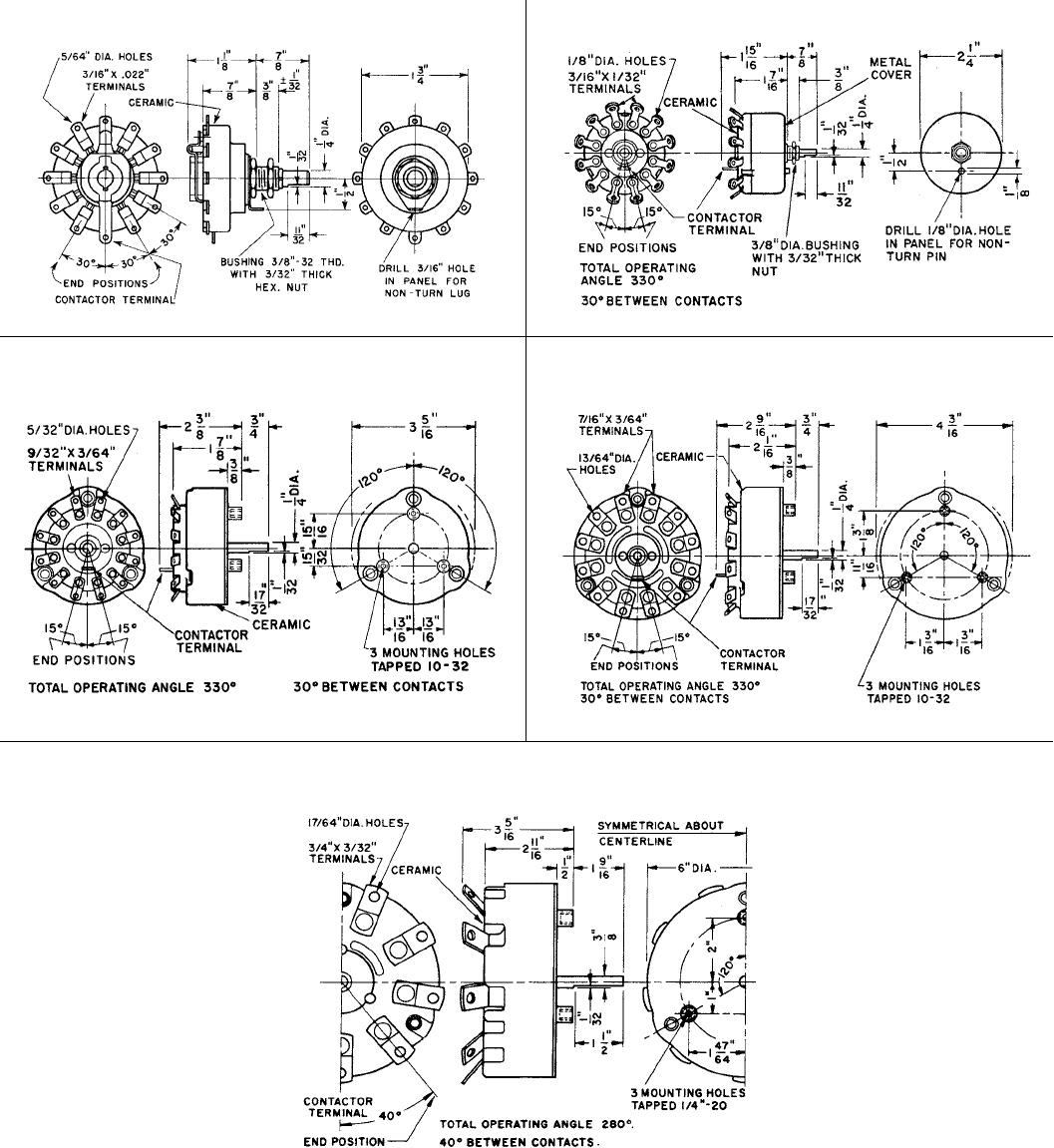
Mounting
Model 711: Using
3
/8-32 bushing
for
1
/8” thick maximum panel.
Four non-turn lug positions are
possible on the single, unen-
closed switch. Recesses in body
of switch permit positioning of
non-turn washer at “12, 3, 6 and
9 o’clock.”
3
/16 “ hole for non-turn
washer. Shaft
1
/4”
Model 111: For
1
/4” panel, maxi-
mum, using
3
/8-32 bushing and
hex nut. A
3
/16” hole is required
for the non-turn washer. Shaft
1
/4”
Model 212: Using
3
/8-32 threaded
bushing and hex nut. A
5
/32” hole
is required for the non-turn pin.
Shaft
1
/4”
Model 312: For
1
/4” panel, maxi-
mum, use three 10-32 flat-head
machine screws
3
/8” long. Shaft
1
/4”
Model 412: For
1
/4” panel, maxi-
mum, use three 10-32 flat-head
machine screws
3
/8” long. A
5
/16” hole in panel is required for
shaft.
Model 608: For 1” panel, maxi-
mum, three flat-head machining
screws
1
/4-20, 1
1
/4” long. Drill
a
7
/16” hole in panel for shaft.
Shaft
3
/8”
NOTE: Since all tap switches are
electro-mechanical devices, they
are subject to wear and, there-
fore, have a finite life.
Typical
tandem model
Model 711
Typical
ceramic style
See page 82 for knobs,
dials, and other hardware
3 60°
4 90°
5 120°
6 150°
7 180°
8 210°
9 240°
10 270°
11 300°
12 330°
Number of taps*
711-* Single unit
Total rotation
711-
*-T2 2 in tandem
711-
*-T3 3 in tandem
111-
* Single unit
111-
*-T2 2 in tandem
212-
* Single unit
212-*-T2 2 in tandem
212-
*-T3 3 in tandem
312-
* Single unit
312-
*-T2 2 in tandem
312-*-T3 3 in tandem
412-
* Single unit
412-
*-T2 2 in tandem
412-
*-T3 3 in tandem
Model 711
7A - 125V
Model 111
15A - 125V
Model 212
20A - 150V
Model 312
30A - 300V
Model 412
50A - 300V
3 80°
4 120°
5 160°
6 200°
7 240°
8 280°
608-* Single unit
608-
*-T2 2 in tandem
608-
*-T3 3 in tandem
Model 608
100A - 300V
= Non-standard values subject to minimum handling charge per item
* Insert number of taps at asterisk for complete part number (e.g. 111-3-T2)
Number of taps*
Total rotation
Check product availability at www.ohmite.com