PCAN
www.vishay.com
Vishay Dale Thin Film
Revision: 19-Apr-16
1
Document Number: 60125
For technical questions, contact: thinfilm@vishay.com
THIS DOCUMENT IS SUBJECT TO CHANGE WITHOUT NOTICE. THE PRODUCTS DESCRIBED HEREIN AND THIS DOCUMENT
ARE SUBJECT TO SPECIFIC DISCLAIMERS, SET FORTH AT www.vishay.com/doc?91000
High Power Aluminum Nitride, Wraparound Surface Mount,
Precision Thin Film Chip Resistor (up to 6 W)
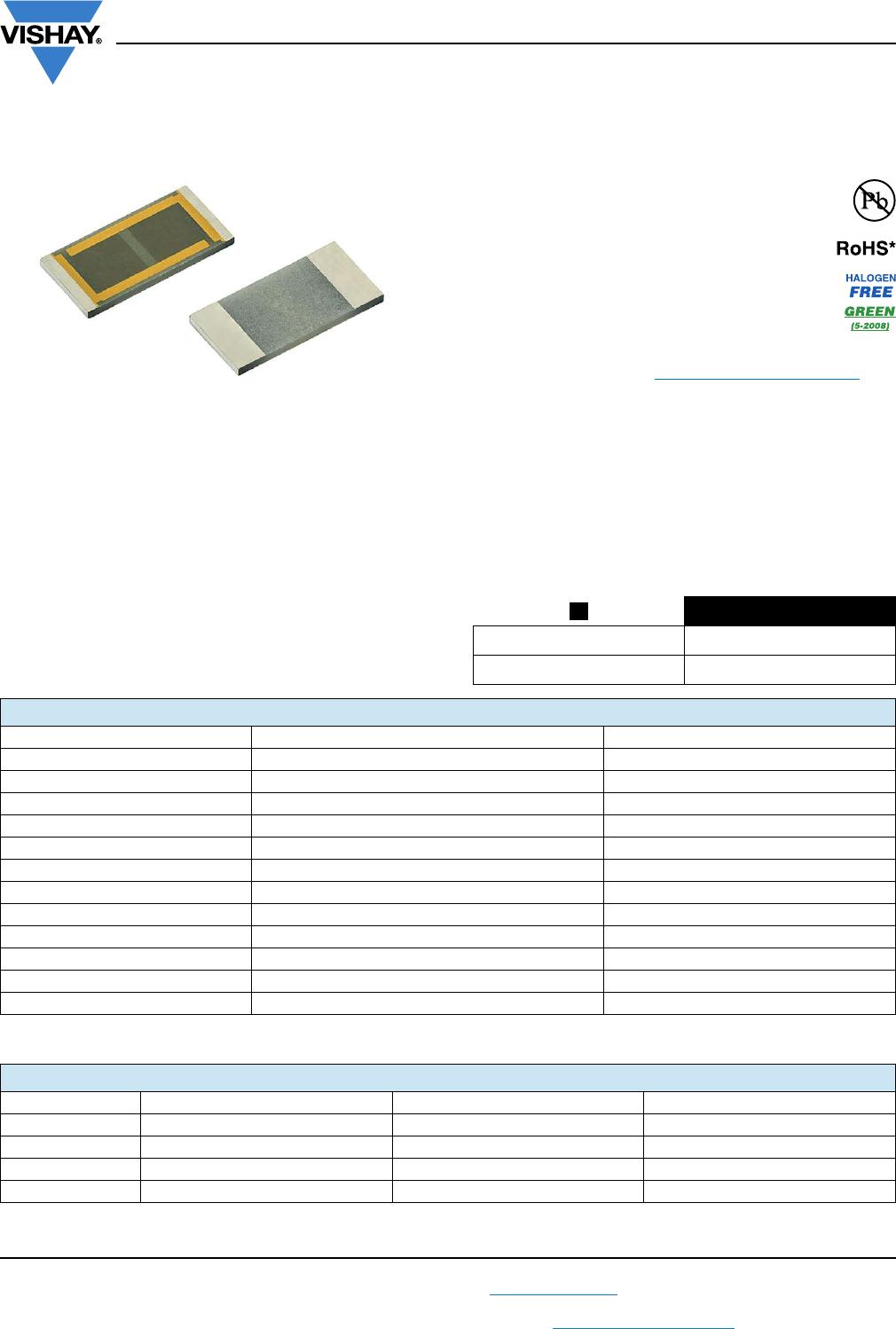
PCAN series chip resistors are designed on aluminum
nitride ceramic substrates with enlarged backside
terminations to reduce the thermal resistance between the
topside resistor layer and the solder joint on the end users
circuit assembly.
Actual power handling capability is limited by the end user
mounting process. As with any high power chip resistor the
ability to remove the heat is critical to the overall
performance of the device.
FEATURES
• High thermal conductivity aluminum nitride
substrate
• Power rating up to 6.0 W
• Resistance range 2 to 30.1 k
• Resistor tolerance to ± 0.1 %
• TCR to ± 25 ppm/°C
• Flame resistant UL 94 V-0
• Material categorization: for definitions of
compliance please see www.vishay.com/doc?99912
Note
*
This datasheet provides information about parts that are
RoHS-compliant and / or parts that are non-RoHS-compliant. For
example, parts with lead (Pb) terminations are not RoHS-compliant.
Please see the information / tables in this datasheet for details.
APPLICATIONS
• Power supplies
• Power switching
• Braking system
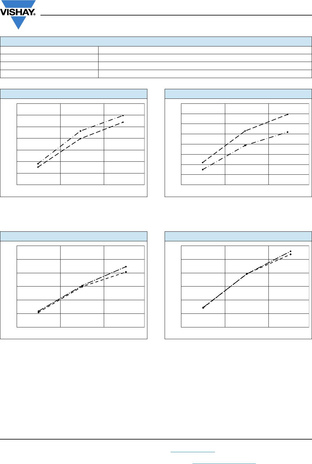
TYPICAL PERFORMANCE
Note
(1)
Dependant on component mounting by user.
Note
(2)
Dependant on component mounting by user.
ABSOLUTE
TCR 25
TOL. 0.1
Available
Available
Available
STANDARD ELECTRICAL SPECIFICATIONS
TEST SPECIFICATIONS CONDITIONS
Material Passivated nichrome -
Resistance Range 2 to 30.1 k -
TCR: Absolute 25 ppm/°C (standard) and 100 ppm/°C -
Tolerance: Absolute 0.1 %, 0.25 %, 0.5 %, 1.0 % and 5.0 % -55 °C to +150 °C
Power Rating: Resistor 0.5 W to 6.0 W
(1)
Maximum at +70 °C
Stability: Absolute R 1.0 % 1000 h at +70 °C
Voltage Coefficient < 0.1 ppm/V -
Working Voltage 75 V to 200 V -
Operating Temperature Range -55 °C to +155 °C -
Storage Temperature Range -55 °C to +155 °C -
Noise < -30 dB -
Shelf Life Stability: Absolute ± 0.01 % 1 year at +25 °C
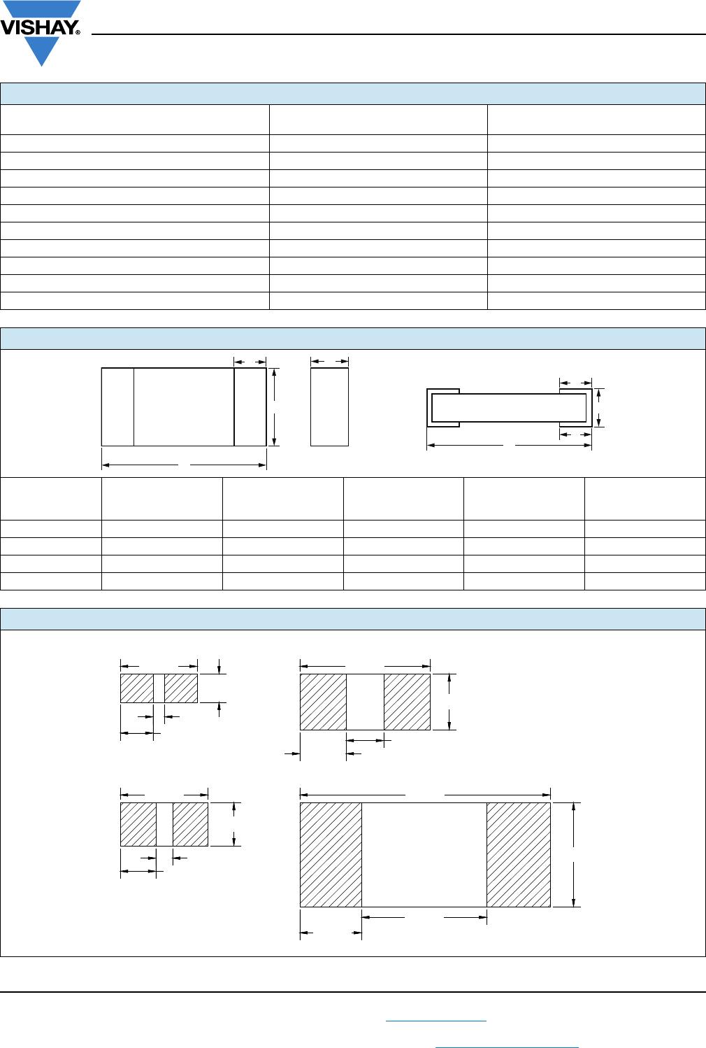
COMPONENT RATINGS
CASE SIZE POWER RATING (mW) WORKING VOLTAGE (V) RESISTANCE RANGE ()
0603 500
(2)
75 2 to 30.1K
0805 1000
(2)
100 2 to 30.1K
1206 2000
(2)
200 2 to 30.1K
2512 6000
(2)
200 2 to 30.1K