NBC12429, NBC12429A
http://onsemi.com
9
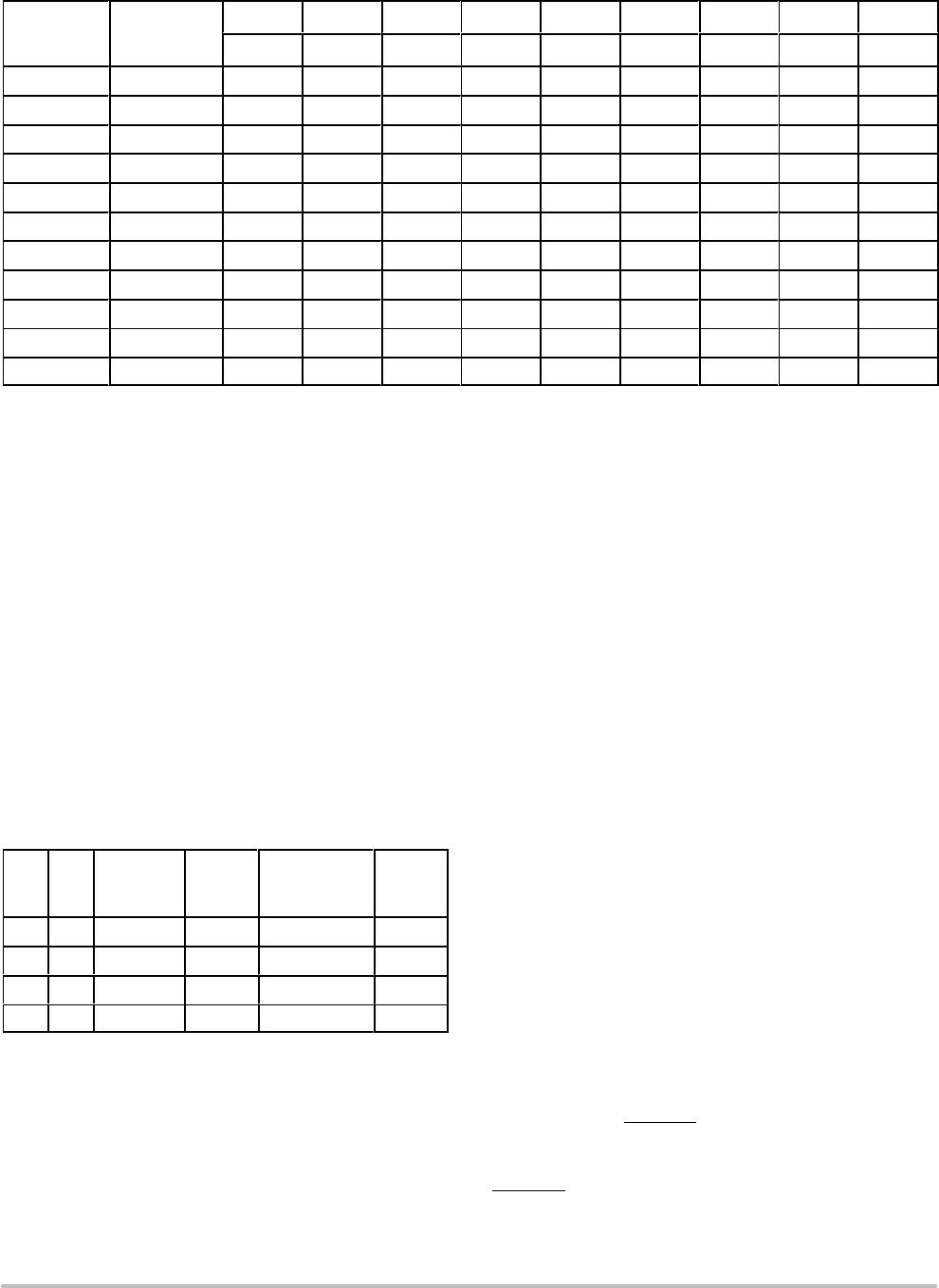
Table 9. PROGRAMMING VCO FREQUENCY FUNCTION TABLE WITH 16 MHZ CRYSTAL
VCO
Frequency
(MHz)
M
Count
Divisor
256 128 64 32 16 8 4 2 1
M8 M7 M6 M5 M4 M3 M2 M1 M0
200 200 0 1 1 0 0 1 0 0 0
201 201 0 1 1 0 0 1 0 0 1
202 202 0 1 1 0 0 1 0 1 0
203 203 0 1 1 0 0 1 0 1 1
• • • • • • • • • • •
• • • • • • • • • • •
• • • • • • • • • • •
397 397 1 1 0 0 0 1 1 0 1
398 398 1 1 0 0 0 1 1 1 0
399 399 1 1 0 0 0 1 1 1 1
400 400 1 1 0 0 1 0 0 0 0
PROGRAMMING INTERFACE
Programming the NBC12429 and NBC12429A is
accomplished by properly configuring the internal dividers
to produce the desired frequency at the outputs. The output
frequency can by represented by this formula:
FOUT + (F
XTAL
B 16) M B N
(eq. 1)
where F
XTAL
is the crystal frequency, M is the loop divider
modulus, and N is the output divider modulus. Note that it
is possible to select values of M such that the PLL is unable
to achieve loop lock. To avoid this, always make sure that M
is selected to be 200 ≤ M ≤ 400 for a 16 MHz input reference.
Assuming that a 16 MHz reference frequency is used the
above equation reduces to:
F
OUT
+ M B N
(eq. 2)
Substituting the four values for N (1, 2, 4, 8) yields:
Table 10. Programmable Output Divider Function
N1 N0 N Divider F
OUT
Output
Frequency
Range (MHz)*
F
OUT
Step
0 0 B1 M 200−400 1 MHz
0 1 B2 M B 2 100−200 500 kHz
1 0 B4 M B 4 50−100 250 kHz
1 1 B8 M B 8 25−50 125 kHz
*For crystal frequency of 16 MHz.
The user can identify the proper M and N values for the
desired frequency from the above equations. The four output
frequency ranges established by N are
200 MHz − 400 MHz, 100 MHz − 200 MHz,
50 MHz − 100 MHz and 25 MHz − 50 MHz, respectively.
From these ranges, the user will establish the value of N
required. The value of M can then be calculated based on
Equation 1. For example, if an output frequency of
131 MHz was desired, the following steps would be taken to
identify the appropriate M and N values. 131 MHz falls
within the frequency range set by an N value of 2; thus, N
[1:0] = 01. For N = 2, F
OUT
= M ÷ 2 and M = 2 x F
OUT
.
Therefore,
M + 131 2 + 262, soM[8 : 0] + 100000110.
Following this same procedure, a user can generate any
whole frequency desired between 25 and 400 MHz. Note
that for N > 2, fractional values of F
OUT
can be realized. The
size of the programmable frequency steps (and thus, the
indicator of the fractional output frequencies achievable)
will be equal to F
XTAL
÷ 16 ÷ N.
For input reference frequencies other than 16 MHz, see
Table 11, which shows the usable VCO frequency and
M divider range.
The input frequency and the selection of the feedback
divider M is limited by the VCO frequency range and
F
XTAL
. M must be configured to match the VCO frequency
range of 200 MHz to 400 MHz in order to achieve stable
PLL operation.
M
min
+ f
VCOmin
B (f
XTAL
B 16) and
(eq. 3)
M
max
+ f
VCOmax
B (f
XTAL
B 16)
(eq. 4)
The value for M falls within the constraints set for PLL
stability. If the value for M fell outside of the valid range, a
different N value would be selected to move M in the
appropriate direction.
The M and N counters can be loaded either through a
parallel or serial interface. The parallel interface is
controlled via the P_LOAD
signal such that a LOW to HIGH
transition will latch the information present on the M[8:0]
and N[1:0] inputs into the M and N counters. When the
P_LOAD
signal is LOW, the input latches will be
transparent and any changes on the M[8:0] and N[1:0] inputs
will affect the F
OUT
output pair. To use the serial port, the

