HFBR-0539Z Evaluation Kit
DC to 12 MBd Probus 650 nm Fiber Optics Eval Kit
User Guide
Introduction
HFBR-0539Z evaluation kit is used to evaluate Avago ber optic device HFBR-1515BZ and HFBR-2515BZ. The evaluation
kit is equipped with necessary documents and accessories to ease product evaluation and verication.
Evaluation Kit
HFBR-0539Z contains:
1. Evaluation board
2. HFBR-1515BZ and HFBR-2515BZ unit
3. HCS® Cable with ST connector
4. HFBR-1515BZ /2515BZ datasheet
5. User guide document
Evaluation Board
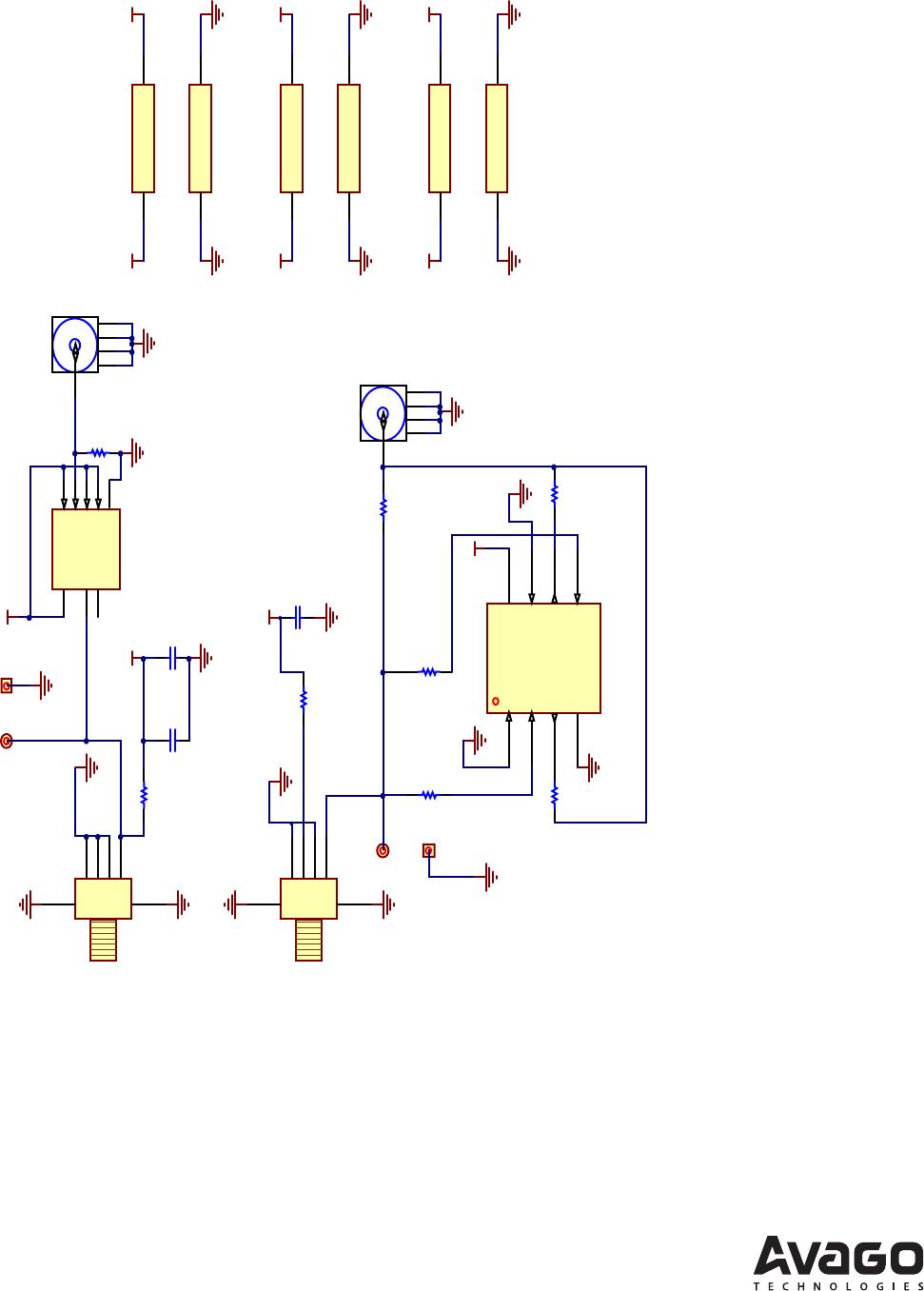
The basic evaluation board that you receive from Avago incorporates transmitter driver IC SN75451BD, some passive
components, and SMA connectors for the TX input (TXD) and RX output (RXD) port connection. This basic evaluation
board allows you to connect waveform/pattern generator to the TXD with TTL input signal. Receiver’s output signal can
be monitored from the RXD or RXout with oscilloscope by using high impedance setting.
Initial Setup
1. Connect 5 V supply voltage to TXVCC and RXVCC
2. Connect 0 V to TXGND and RXGND
3. Connect TXD to pattern generator output
4. Connect RXout to Oscilloscope with high impedance probe
Bit Error Rate Test Setup
Though the transmitter driver IC’s input and receiver’s output is based on TTL logic (high impedance), the board can be
modied to connect 50 ohm load instrument by doing the following steps:
1. Put R2 (50 ohm resistor).
2. Remove R3 (0 ohm resistor).
3. Put R4 (0 ohm resistor) and R7 (50 ohm resistor).
4. Put U3 (SN74LVC2G125).
5. Connect BVCC (5 V) and BGND (0 V).
HCS® is a trademark of OFS