RClamp0582BQ
Final Datasheet Rev 3.0
Revision date 11/4/2016
Application Information
2 1
3
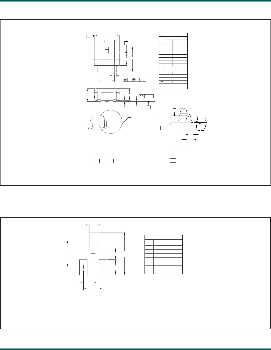
Figure 1. Pin Conguration
Device Connection Options
This device is optimized for protection of two high speed
dta lines. The device is connected as follows: Protection
of two lines is achieved by connecting data lines at pins
1 & 2. Pin 3 is connected to ground. The connection to
ground should be made directly to a ground plane. The
path length should also be kept as short as possible to
minimize parasitic inductance.
Matte Tin Lead Finish
Matte tin has become the industry standard lead-free
replacement for SnPb lead nishes. A matte tin nish
is composed of 100% tin solder with large grains. Since
the solder volume on the leads is small compared to the
solder paste volume that is placed on the land pattern of
the PCB, the reow prole will be determined by the re-
quirements of the solder paste. Therefore, these devices
are compatible with both lead-free and SnPb assembly
techniques. In addition, unlike other lead-free composi-
tions, matte tin does not have any added alloys that can
cause degradation of the solder joint.