Design and specifications are each subject to change without notice. Ask factory for the current technical specifications before purchase and/or use.
Should a safety concern arise regarding this product, please be sure to contact us immediately.
Anti-Surge Thick Film Chip Resistors
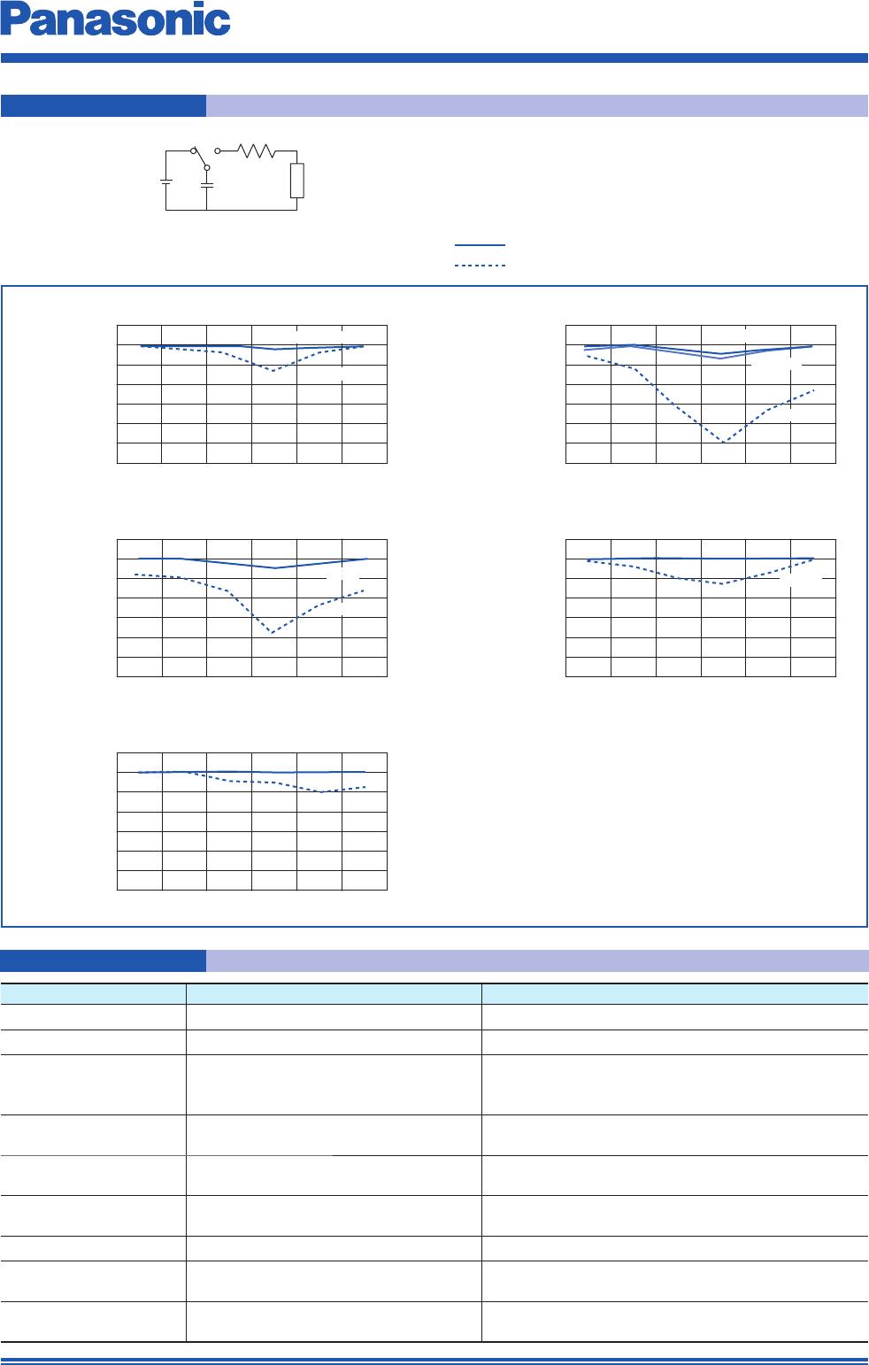
Change Ratio of
Resistance Value
Change Ratio of
Resistance Value
Change Ratio of
Resistance Value
Change Ratio of
Resistance Value
-30%
-25%
-15%
-10%
-5%
0%
5%
-20%
-30%
-25%
-15%
-10%
-5%
0%
5%
-20%
-30%
-25%
-15%
-10%
-5%
0%
5%
-20%
ERJP03, PA3 (0603 inch /1608 mm size)
ERJP08 (1206 inch / 3216 mm size)ERJP06 (0805 inch / 2012 mm size)
ERJP14 (1210 inch / 3225 mm size)
-30%
-25%
-15%
-10%
-5%
0%
5%
-20%
ERJ6G
ERJP06
ERJ3G
ERJP14
ERJ14
ERJP08
ERJ8G
ERJP03
ERJPA3
Change Ratio of
Resistance Value
-30%
-25%
-15%
-10%
-5%
0%
5%
-20%
ERJPA2 (0402 inch /1005 mm size)
ERJ2G
ERJPA2
10 Ω 100 Ω 1k Ω 10k Ω 100k Ω 1M Ω
10 Ω 100 Ω 1k Ω 10k Ω 100k Ω 1M Ω
10 Ω 100 Ω 1k Ω 10k Ω 100k Ω 1M Ω
10 Ω 100 Ω 1k Ω 10k Ω 100k Ω 1M Ω
10 Ω 100 Ω 1k Ω 10k Ω 100k Ω 1M Ω
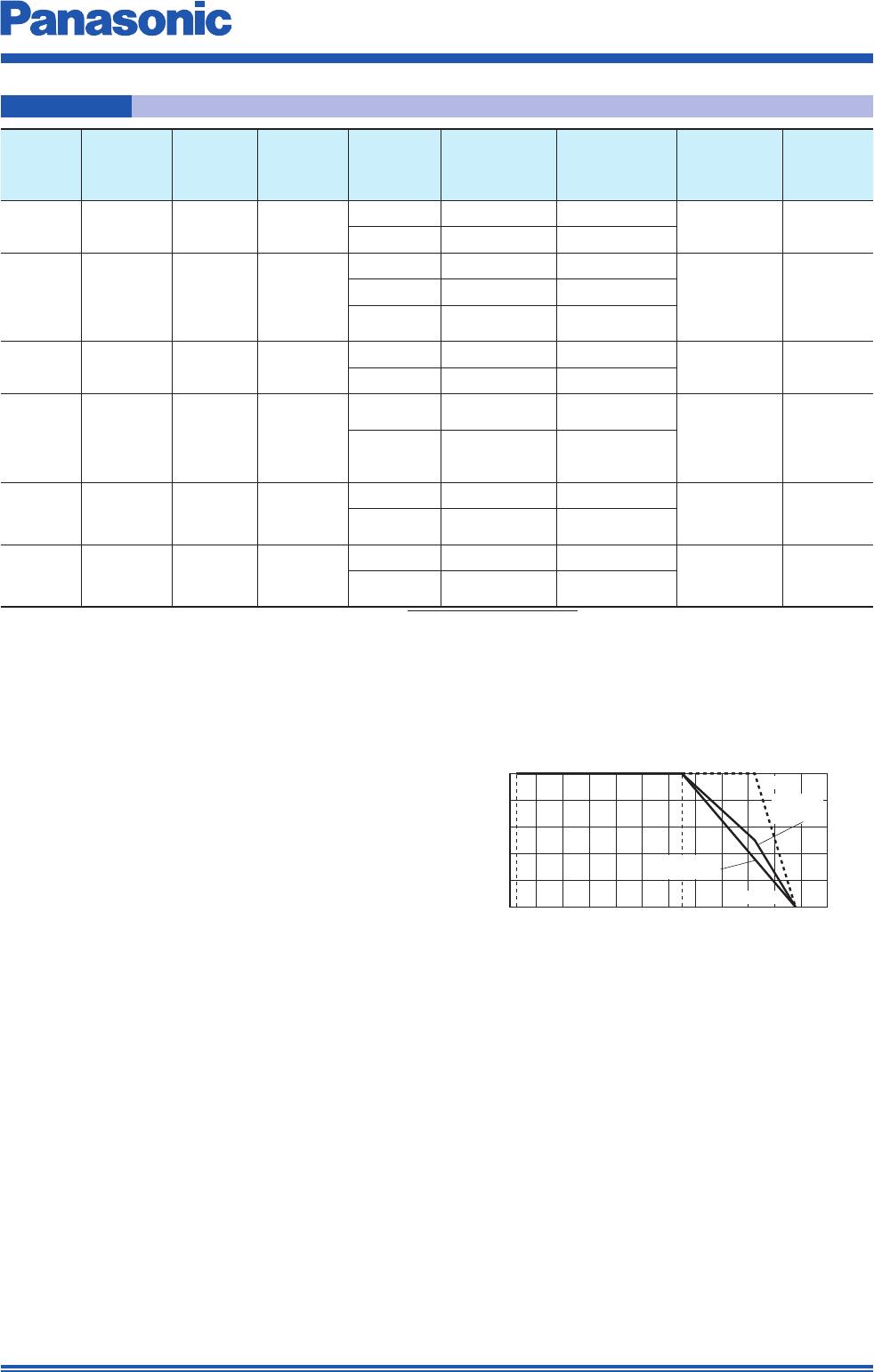
R=0 Ω(≤ 1.5k Ω)/150 Ω(> 1.5k Ω)
C=150p F
Sample
E
Anti-Surge Thick Film Chip Resistors(ERJP Type)
Thick Film Chip Resistors(ERJ Type)
ESD Characteristic
0402 inch size : E=±1k V
0603, 0805, 1206, 1210 inch size : E=±3k V
Test Item Performance Requirements
Test Conditions
Resistance Within Specifi ed Tolerance
20 °C
T. C. R. Within Specifi ed T. C. R. +25 °C/+155 °C (ERJPA2 : +125 °C)
Overload
±2%
Only when it is ERJP03 (D), P14 (D) : ±0.5%
ERJP06 : Rated Voltag×1.77, 5 s
ERJPA2, ERJPA3, ERJP08 : Rated Voltag×2.0, 5 s
ERJP03, ERJP14 : Rated Voltag×2.5, 5 s
Resistance to
Soldering Heat
D : ±0.5%, F, J : ±1% 270 °C, 10 s
Rapid Change of
Temperature
±1% –55 °C (30 min.) / +155 °C (30 min.) , 100 cycles
High Temperature
Exposure
±1% +155 °C, 1000 h
Damp Heat, Steady State
±1% 60 °C, 90% to 95%RH, 1000 h
Load Life in Humidity
±3%
Only when it is ERJP03 (D), P14 (D) : ±1%
60 °C, 90% to 95%RH,
Rated Voltage, 1.5 h ON / 0.5 h OFF cycle, 1000 h
Endurance at 70 °C
±3%
Only when it is ERJP03 (D), P14 (D) : ±1%
70 °C, Rated Voltage,
1.5 h ON / 0.5 h OFF cycle, 1000 h
Performance
Nov. 201711