Design and specifi cations are each subject to change without notice. Ask factory for the current technical specifi cations before purchase and/or use.
Should a safety concern arise regarding this product, please be sure to contact us immediately.
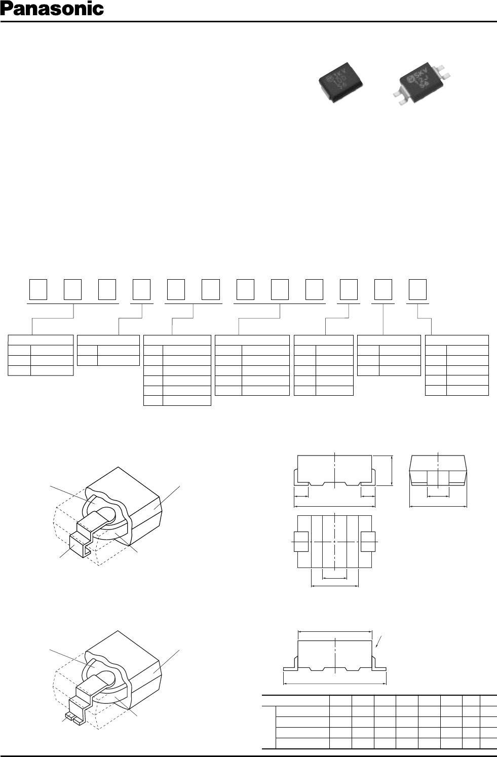
High Voltage Ceramic Capacitors (SMD)
E
C
D
r
A
Wt
B
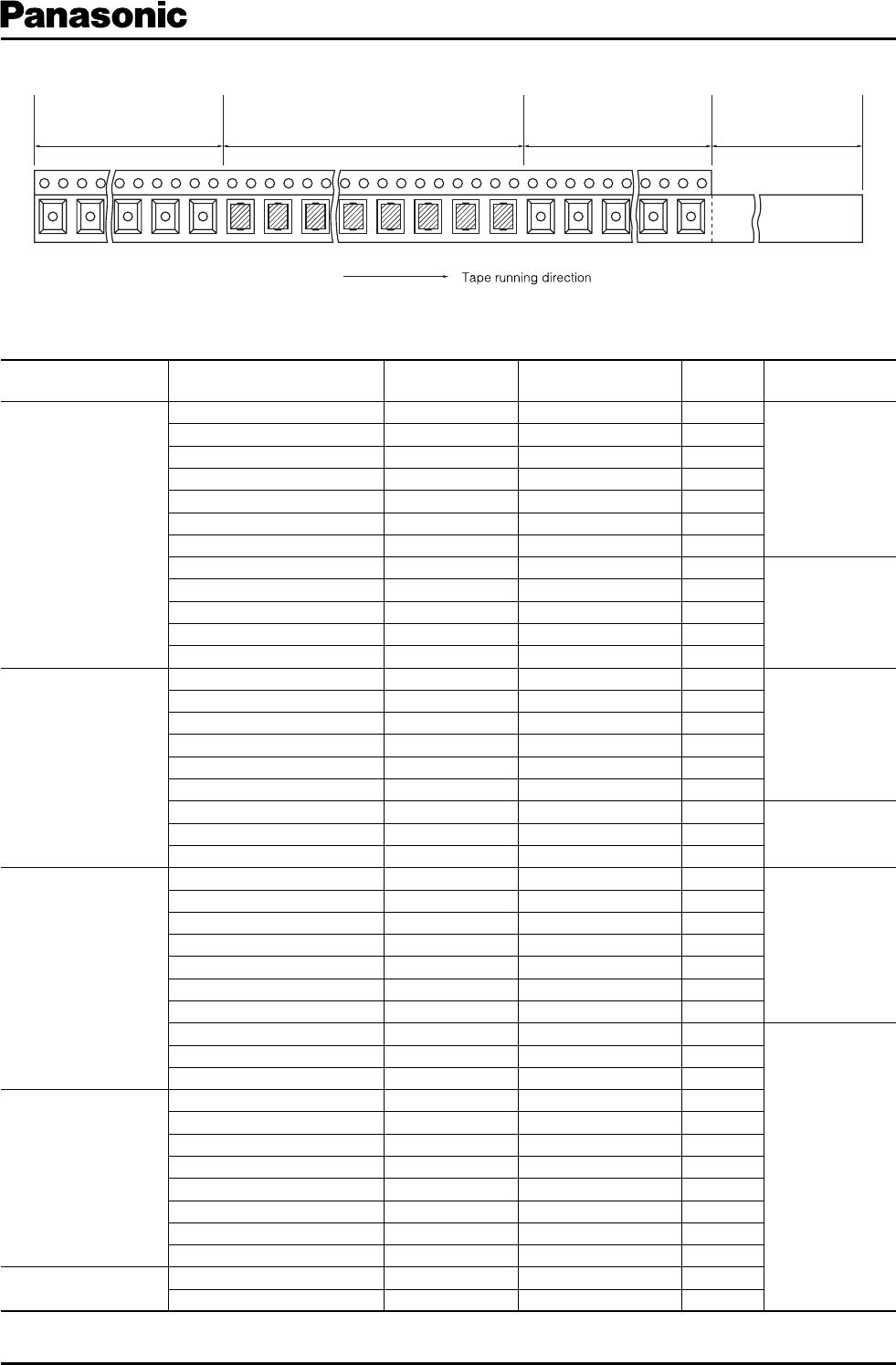
Chip component Tape running
direction
(W=12 mm)
Feeding hole Chip pocket
t
2
t1
P2 P0
P1
φD0
A
B
F
W
E
Chip component Tape running
direction
Feeding hole
Chip pocket
t2
t1
P2 P0
P1
φD0
F
W
E
A
B
■ Specifi cations
Characteristics
Operating Temperature Range
Char. SL/GP Char. B/Y5P
–25 to 105 °C
Rated Voltage2 to 3 kVDC 4 to 5 kVDC 5 kVDC 1 to 2 kVDC
Dielectric
Withstanding Voltage
200 % of Rated Voltage
for 1 to 5 seconds
150 % of Rated Voltage
for 1 to 5 seconds
120 % of Rated Voltage
for 1 to 5 seconds
200 % of Rated Voltage
for 1 to 5 seconds
Capacitance Within the specifi ed tolerance, when measured
at 1 MHz±20 %, 1 to 5 Vrms. and 20 °C
Within the specifi ed tolerance, when measured
at 1 kHz±20 %, 1 to 5 Vrms. and 20 °C
Q or Dissipation Factor
(tan
δ
)
30 pF or under Q
>
400+20 C (C:Cap.pF)
over 30 pF Q
>
1000
at 1 MHz±20 %,1 to 5 Vrms. and 20 °C
tan
δ
<
0.025
at 1 kHz±20 %,1 to 5 Vrms. and 20 °C
Insulation Resistance 10000 M
액
min. at 500 VDC and 1 minute electrifi cation
Temperature
Characteristics
Temperature Coeffi cient:
+350 to –1000 ppm/ °C
(Temperature Range : 20 to 85 °C)
Max. Cap. Change:±10 %
(Temperature Range : –25 to 85 °C)
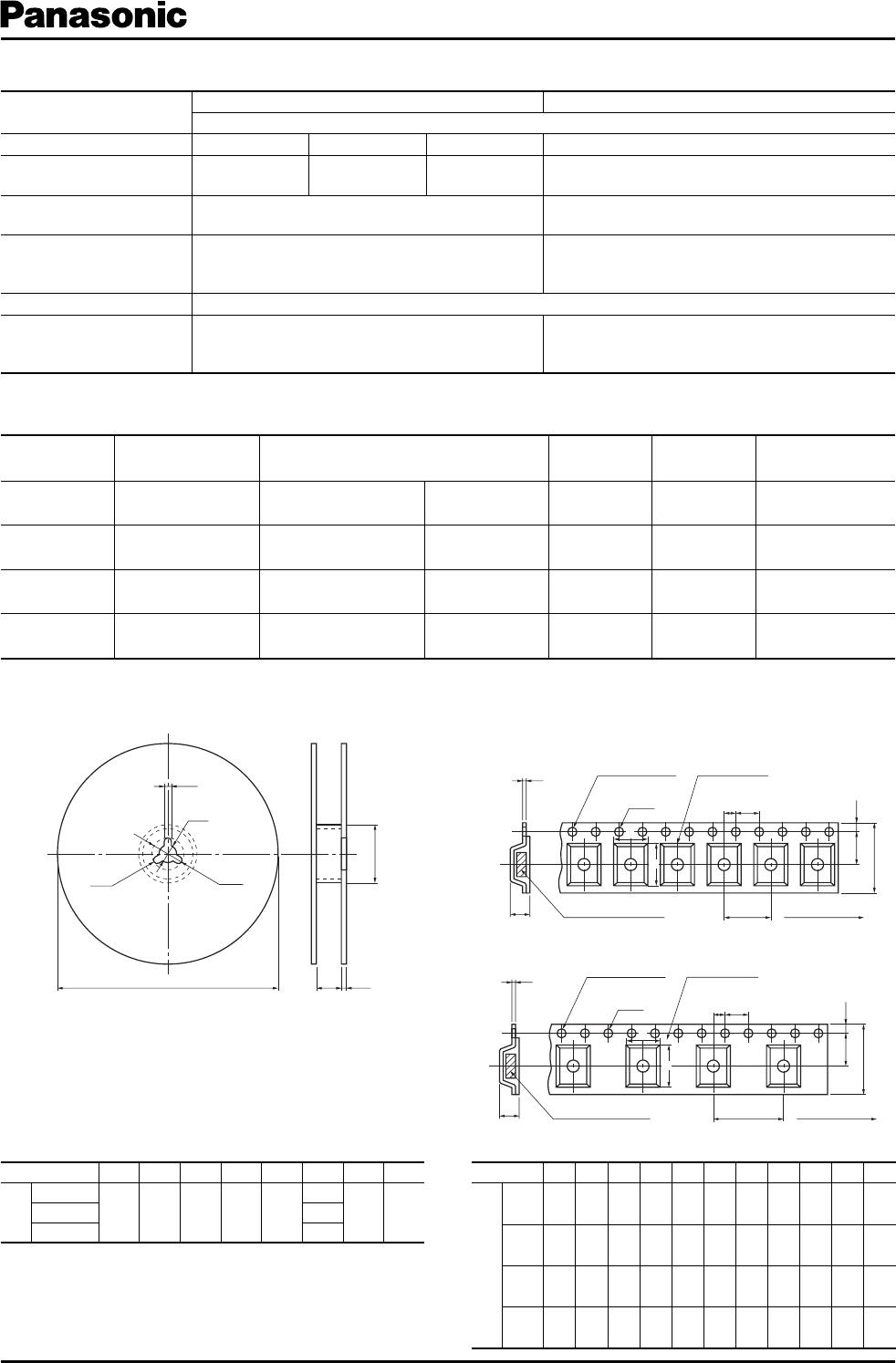
■ Packaging Methods (Taping)
●
Minimum Quantity/Packing Unit
●
Reel
●
Embossed Carrier Taping
style 1, 3, 4
style 2
Type Packaging Style Part Number
Minimum Packing
Quantity
Packing Quantity
in Carton
Carton Dimensions
in mm L
҂
W
҂
H
1 to 5 kVDC
(style 1)
Embossed Carrier
Taping
EC
첸
T3
첸첸첸첸첸첸
5 to 470 pF
2000
pcs./reel
6000 pcs. 350
҂
350
҂
62
5 kVDC
(style 2)
Embossed Carrier
Taping
ECCT3H
첸첸첸첸첸
M
5 to 27 pF
2000
pcs./reel
4000 pcs. 350
҂
350
҂
62
4 kVDC
(style 3)
Embossed Carrier
Taping
ECCT3G
첸첸첸
JG2
10 to 27 pF
3000
pcs./reel
9000 pcs. 350
҂
350
҂
62
5 kVDC
(style 4)
Embossed Carrier
Taping
ECCT3H
첸첸첸첸첸
Y
5 to 15 pF
3000
pcs./reel
6000 pcs. 350
҂
350
҂
62
Unit:(mm)
Symbol A B W F E P
1
P
2
P
0
φ
D
0
t
1
t
2
Dim.
(mm)
style1
6.5
±0.2
7.5
±0.2
12.0
±0.3
5.5
±0.1
1.75
±0.10
8.0
±0.1
2.0
±0.1
4.0
±0.1
1.5
+0.1
–0
0.3
±0.1
3.2
±0.3
style2
6.65
±0.20
11.2
±0.2
24.0
±0.3
11.5
±0.1
1.75
±0.10
12.0
±0.1
2.0
±0.1
4.0
±0.1
1.5
+0.1
–0
0.3
±0.1
3.2
±0.3
style3
4.8
±0.2
6.0
±0.2
12.0
±0.3
5.5
±0.1
1.75
±0.10
8.0
±0.1
2.0
±0.1
4.0
±0.1
1.5
+0.1
–0
0.3
±0.1
2.8
±0.3
style4
4.7
±0.2
10.0
±0.5
16.0
±0.3
7.5
±0.1
1.75
±0.10
8.0
±0.1
2.0
±0.1
4.0
±0.1
1.5
+0.1
–0
0.3
±0.1
2.85
±0.30
Unit:(mm)
Symbol
ABCDEWt r
Dim.
(mm)
style 1, 3
330
±5
60
min.
13.0
±0.5
21.0
±1.0
2.0
±0.5
13.5
±1.5
2.0
±0.5
R1.0
style 2
25.5
±1.5
style 4
17.5
±1.5
Dec. 2007