MAX900–MAX903
High-Speed, Low-Power Voltage Comparators
_______________________________________________________________________________________ 5
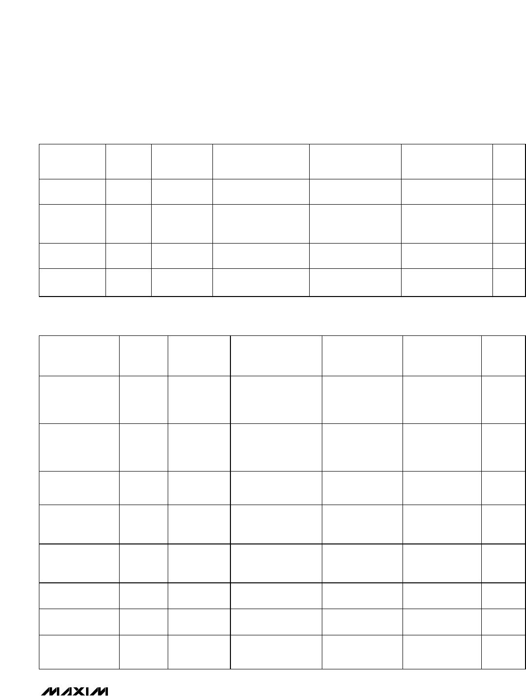
ELECTRICAL CHARACTERISTICS (continued)
(V
CC
= +5V, V
EE
= -5V, V
DD
= +5V, LE1–LE4 = logic high, T
A
= full operating temperature, unless otherwise noted.)
MAX900A/MAX901A/
MAX900B/MAX901B
MAX902 MAX903
PARAMETER SYMBOL CONDITIONS
MIN TYP MAX MIN TYP MAX MIN TYP MAX
UNITS
Positive Analog
Supply Current
I
CC
(Note 7) 10 25 5 12 2.5 6 mA
Negative Analog
Supply Current
I
EE
(Note 7) 7 20 3.5 10 2 5 mA
Digital Supply
Current
I
DD
(Note 7) 4 10 2 5 1 2.5 mA
Power
Dissipation
P
D
V
CC
= V
DD
=
+5V, V
EE
= 0
70 105 35 55 18 28 mW
TIMING CHARACTERISTICS
(V
CC
= +5V, V
EE
= -5V, V
DD
= +5V, LE1–LE4 = logic high, T
A
= full operating temperature, unless otherwise noted.)
MAX900A/MAX901A
MAX900B/MAX901B/
MAX902/MAX903
PARAMETER SYMBOL CONDITIONS
MIN TYP MAX MIN TYP MAX
UNITS
Input-to-Output High
Response Time
t
pd+
V
OD
= 5mV,
C
L
= 15pF,
I
O
= 2mA
(Note 4)
10 15 10 15 ns
Input-to-Output Low
Response Time
t
pd-
V
OD
= 5mV,
C
L
= 15pF,
I
O
= 2mA
(Note 4)
10 15 10 15 ns
Difference in Response
Time Between Outputs
∆t
pd
(Notes 4, 5) 1 3 1 3 ns
Note 1: The input common-mode voltage and input signal voltages should not be allowed to go negative by more than 0.2V below
V
EE
. The upper-end of the common-mode voltage range is typically V
CC
- 2V, but either or both inputs can go to a maximum
of V
CC
+ 0.2V without damage.
Note 2: Tested for +4.75V < V
CC
< +5.25V, and -5.25V < V
EE
< -4.75V with V
DD
= +5V, although permissible analog power-supply
range is +4.75V < V
CC
< +10.5V for single-supply operation with V
EE
grounded.
Note 3: Specification does not apply to MAX901.
Note 4: Guaranteed by design. Times are for 100mV step inputs (see Propagation Delay Characteristics in Figures 2 and 3).
Note 5: Maximum difference in propagation delay between any of the four comparators in the MAX900–MAX903.
Note 6: See Timing Diagram (Figure 2). Owing to the difficult and critical nature of switching measurements involving the latch,
these parameters cannot be tested in a production environment. Typical specifications listed are taken from measurements
using a high-speed test-jig.
Note 7: I
CC
tested for +4.75V < V
CC
< +10.5V with V
EE
grounded. I
EE
tested for -5.25V < V
EE
< -4.75V with V
CC
= +5V. I
DD
tested
for +4.75V < V
DD
< +5.25V with the worst-case condition of all four comparator outputs at logic low.