TXS2SL-L-6V-Z

TX-S
REFERENCE DATA
1. Maximum switching capacity 2. Life curve 3. Mechanical life
Tested sample: TXS2-4.5V, 10 pcs.
Operating speed: 180 cpm
30
100
200
1.0
0.5
0.4
0.3
0.2
Contact current, A
DC resistive load
(cos = 1)
φ
Contact voltage, V
0 0.5 1.0
100
10
Switching current, A
No. of operations ×10
4
30V DC
resistive load
0
10
100 5,0001,00010
20
30
40
50
60
70
80
90
100
Min.
No. of operations, ×10
4
Ratio against the rated voltage, %V
Pick-up voltage
Drop-out voltage
Max.
Min.
Max.
4. Electrical life (1 A 30 V DC resistive load)
Tested sample: TXS2-4.5V, 6 pcs.
Operating speed: 20 cpm
Change of pick-up and drop-out voltage Change of contact resistance
5-(1). Coil temperature rise
Tested sample: TXS2-4.5V, 6 pcs.
Point measured: Inside the coil
Ambient temperature: 25°C 77°F, 70°C 158°F
2005
Max.
Min.
Min.
0
10
20
30
40
50
60
70
80
90
100
10 15
Max.
No. of operations, ×10
4
Ratio against the rated voltage, %V
Pick-up voltage
Drop-out voltage
2005
Min.
0
10
20
30
40
50
60
70
80
90
100
10 15
Max.
No. of operations, ×10
4
Contact resistance, m
10
30
10090 120 150 160
0
20
110 130 140
1A
1A
0A
0A
Coil applied voltage, %V
Temperature rise, °C
Room temperature :x
+70°C +158°F :x
5-(2). Coil temperature rise
Tested sample: TXS2-24V, 6 pcs.
Point measured: Inside the coil
Ambient temperature: 25°C 77°F, 70°C 158°F
6-(1). Operate and release time (with diode)
Tested sample: TXS2-4.5V, 10 pcs.
6-(2). Operate and release time (without diode)
Tested sample: TXS2-4.5V, 10 pcs.
10
30
10090 120 150 160
0
20
110 130 140
1A
1A
0A
0A
Coil applied voltage, %V
Temperature rise, °C
Room temperature :x
+70°C +158°F :x
1
4
3
2
6
7
80 100 120
0
5
90 110
Max.
Max.
Min.
Min.
Coil applied voltage, %V
Operate and release time, ms
Operate time
Release time
1
4
3
2
6
7
80 100 120
0
5
90 110
Max.
Max.
Min.
Min.
Operate time
Release time
Coil applied voltage, %V
Operate and release time, ms
7. Ambient temperature characteristics
Tested sample: TXS2-4.5V, 5 pcs.
8-(1). High frequency characteristics
(Isolation)
Tested sample: TXS2-4.5V, 2 pcs.
8-(2). High frequency characteristics
(Insertion loss)
Tested sample: TXS2-4.5V, 2 pcs.
–30
30
20
10
–20
–40 –20 020
x
x
–10
40 60 80
Ambient
temperature, °C
Rate of change, %
Drop-out
voltage
Pick-up voltage
50
10 100 1,000
100
Frequency, MHz
Isolation, dB
0.6
10 100 1,000
0.2
0.4
1.0
0.8
Frequency, MHz
Insertion loss, dB
All Rights Reserved © COPYRIGHT Panasonic Electric Works Co., Ltd.
Partly Order Discontinued as of August 31, 2011
TX-S
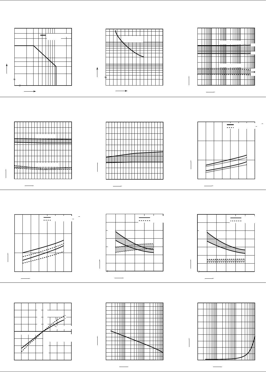
9-(1). Malfunctional shock (single side stable)
Tested sample: TXS2-4.5V, 6 pcs.
9-(2). Malfunctional shock (latching)
Tested sample: TXS2-L2-4.5V, 6 pcs.
10. Thermal electromotive force
Tested sample: TXS2-4.5V, 6 pcs.
Y’
Y
XZ
Z’ X’
Y
Y’
Z’
Z
X
X’
1000m/s
2
1000m/s
2
1000m/s
2
1000m/s
2
1000m/s
2
1000m/s
2
Deenergized condition
Energized condition
1000m/s
2
1000m/s
2
1000m/s
2
1000m/s
2
1000m/s
2
1000m/s
2
Y’
Y
XZ
Z’ X’
Y
Y’
Z’
Z
X
X’
Reset state
Set state
0
2
4
6
8
10
12
14
16
18
20
0
0.15 0.25 0.35 0.45 0.55
Thermal electromotive force, µV
Quantity
x = 0.30
11-(1). Influence of adjacent mounting
Tested sample: TXS2-4.5V, 6 pcs.
11-(2). Influence of adjacent mounting
Tested sample: TXS2-4.5V, 6 pcs.
11-(3). Influence of adjacent mounting
Tested sample: TXS2-4.5V, 6 pcs.
–15
–10
0
–5
5
10
15
ON
ON
ON
OFF
OFF
OFF
10 12 14 16624 8
0
Pick-up voltage
Drop-out voltage
Inter-relay distance , mm inch
Rate of change, % Rate of change, %
.394 .472 .551 .630.236.079 .157 .315
–15
–10
–5
10 12 14 16624 8
0
0
5
10
15
ON
ON
ON
OFF
OFF
OFF
Pick-up voltage
Drop-out voltage
Inter-relay distance , mm inch
Rate of change, % Rate of change, %
.394 .472 .551 .630.236.079 .157 .315
5
10
0
15
Pick-up voltage
Drop-out voltage
Inter-relay distance , mm inch
–15
–10
–5
10 12 14 16624 8
0
Rate of change, % Rate of change, %
ON
ON
ON
OFF
OFF
OFF
ON
OFF
.394 .472 .551 .630.236.079 .157 .315
12. Pulse dialing test
(35 mA 48V DC wire spring relay load)
Tested sample: TXS2-4.5V, 6 pcs.
Change of pick-up and drop-out voltage Change of contact resistance
+
DC48V
458
0.08
µF
0.08
µF
458
4
3
Wire spring relay
0
0
10
20 503010
Max.
Max.
Min.
Min.
20
30
40
50
60
70
80
90
100
40
Pick-up voltage
Drop-out voltage
No. of operation, ×10
4
Ratio against the rated voltage, %V
50
Max.
Min.
0
10
20
30
40
50
60
70
80
90
100
100203040
No. of operation, ×10
4
Contact resistance, m
Note: Data of surface-mount type are the same as those of PC board terminal type.
All Rights Reserved © COPYRIGHT Panasonic Electric Works Co., Ltd.
Partly Order Discontinued as of August 31, 2011
TX-S
DIMENSIONS (mm inch)
1. Standard PC board terminal and Self clinching terminal
Schematic (Bottom view)
2. Surface-mount terminal
Type
External dimensions (General tolerance: ±0.3 ±.012) PC board pattern (Bottom view) (Tolerance: ±0.1 ±.004)
Single side stable and
1 coil latching type
2 coil latching type (L2, LT)
Single side stable and
1 coil latching type
2 coil latching type (L2, LT)
Standard
PC board
terminal
Self
clinching
terminal
Type
External dimensions (General tolerance: ±0.3 ±.012) Suggested mounting pad (Top view) (Tolerance: ±0.1 ±.004)
Single side stable and
1 coil latching type
2 coil latching type (L2, LT)
Single side stable and
1 coil latching type
2 coil latching type (L2, LT)
SA type
SL type
SS type
The CAD data of the products with a CAD Data mark can be downloaded from: http://panasonic-electric-works.net/ac
CAD Data
15.00 7.40
0.25
1.15
.020
5.08 2.54
5.08
0.50
.045 .200 .100
.591 .291
.200
.010
8.20
.323
0.65
.026
3.50
.138
15.00
1.15
.020
5.08 2.54
7.40
5.08
0.25
0.50
.045 .200 .100
.591
.291
.200
.010
8.20
.323
0.65
.026
3.50
.138
5.08
2.54
8-1.0 dia.
10.16
.200
.100
8-.039 dia.
.400
5.08
2.54
10-1.0 dia.
12.7
.200
.100
10-.039 dia.
.500
15.00
7.40
1.15
.020
5.08
2.54
0.25
5.08
0.50
.045 .200
.100
.591
.291
.200
.010
8.20
.323
0.65
.026
3.50
.138
15.00
1.15
.020
0.50
5.08
2.54
.045 .200
.100
7.40
.591
.291
5.08
.200
0.25
.010
8.20
.323
0.65
.026
3.50
.138
(1.15)
(.045)
Single side stable
(Deenergized condition)
1 coil latching
(Reset condition)
2 coil latching (L2)
(Reset condition)
2 coil latching (LT)
(Reset condition)
Direction indication
12 10 9 8
1 3 4 5
+
Direction indication
12 10 9 8
1 3 4 5
+
Direction indication
12 10 9 8 7
1 3 4 5 6
+
+
Direction indication
12 10 9 8 7
1
3 4 5 6
+
+
CAD Data
.591
15
0.65
.026
5.08
.200
5.08
.200
2.54
.100
8.2
.323
0.5
.020
0.25
.010
8.4
.331
9.4±0.5
.370±.020
.291
7.4
.591
15
0.65
.026
5.08
.200
5.08
.200
2.54
.100
8.2
.323
0.5
.020
0.25
.010
8.4
.331
9.4±0.5
.370±.020
.291
7.4
5.08
.200
1
.039
.100
2.54
.124
3.16
7.24
.285
5.08
.200
1
.039
.100
2.54
.124
3.16
7.24
.285
.591
15
0.65
5.08
5.08
.200
2.54
8.2
.323
0.5
0.25
Max.10
.394
9.4±0.5
.370±.020
.291
7.4
.026
.200
.010
.020
.100
.591
15
0.65
5.08
5.08
.200
2.54
8.2
.323
0.5
0.25
Max.10
.394
9.4±0.5
.370±.020
.291
7.4
.026
.200
.010
.020
.100
5.08
.200
1
.039
.100
2.54
.124
3.16
7.24
.285
5.08
.200
1
.039
.100
2.54
.124
3.16
7.24
.285
.591
15
0.65
.026
5.08
.200
5.08
.200
0.25
.010
0.5
.020
8.2
.323
2.54
.100
Max.10
.394
7.4±0.5
.291±.020
.291
7.4
.591
15
0.65
.026
5.08
.200
5.08
.200
0.25
.010
0.5
.020
8.2
.323
2.54
.100
Max.10
.394
7.4±0.5
.291±.020
.291
7.4
5.08
.100
2.54
.200
1
.039
.085
2.16
6.24
.246
5.08
.100
2.54
.200
1
.039
.085
2.16
6.24
.246
All Rights Reserved © COPYRIGHT Panasonic Electric Works Co., Ltd.
Partly Order Discontinued as of August 31, 2011

TXS2SL-L-6V-Z

Mfr. #:
Manufacturer:
Panasonic
Description:
Low Signal Relays - PCB 1A 6VDC 35MW SMD RELAY LATCHING
Lifecycle:
New from this manufacturer.
Delivery:
DHL FedEx Ups TNT EMS
Payment:
T/T Paypal Visa MoneyGram Western Union