Curtis Industries
A Division of Powers Holdings, Inc.
1-800-657-0853
Dimensions are in inches and millimeters
unless otherwise speci¿ed.
Values in parentheses are metric equivalents.
41
BARRIER STYLEHigh Voltage/Current
6SeFi¿Fations:
Center-to-Center Spacing: 7/16" (11.11mm)
Wire Range:
WT – No. 16AWG to No. 8AWG
WTC – No. 22AWG to No. 8AWG
WH – No. 22AWG to No. 4AWG
No. of Terminals: 2 thru 164
Voltage Rating: CSA & UL: 600V
Tightening Torque:
WT, WTC 25 in.-lb.
WH 45 in.-lb. (4-6AWG)
40 in.-lb. (8AWG)
35 in.-lb. (10-14 AWG)
Current Rating: WT, WTC: 50A, WH: 75A
Housing:
Material Phenolic
Continuous Use
Temp. (UL Index) 150°C (302°F)
Flammability Rating 94V-1
Water Absorption
(24 hrs. % wt. gain) 0.5%
Chemical Resistance Resistant to most organic
solvents
Breakdown Voltage: WT WTC WH
Terminal - Terminal 6,300V Typ. 5,100V Typ. 10,500V Typ.
Terminal - Ground 10,100V Typ. 10,100V Typ. 7,700V Typ.
Note: Speci¿cations contained herein are subMect to change
without notice.
Series W Accessories
MARKING STRIPS
White ¿ber marking strip available in two or three-pole lengths
or in pre-punched 100-ft. rolls.
To order, specify:
Part No. 271A11 (2PW)
Part No. 271A13 (3PW)
100-ft. Rolls – Part No. 20W
Pins – Part No. 21W
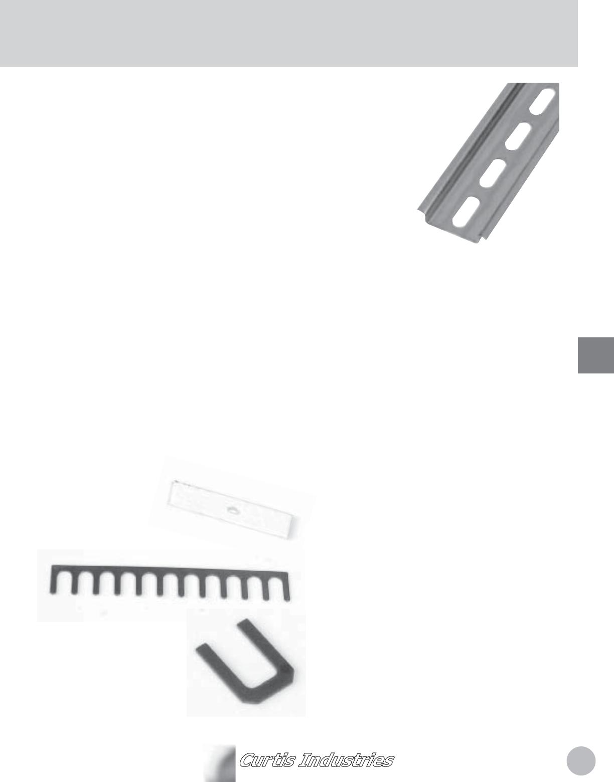
Tracks
Features:
STURD< TRAC. – constructed of heavy steel with zinc-
dichromate plating. Mounting holes are 7/32 inch diameter
and provided continuously on 3/8 inch center-to-center
spacing (SW Series) and 7/16 inch centers (W Series). DIN
mounting holes are slots .248" wide by .709" long on .984"
center-to-center spacing.
EC2N2MICAL STANDARD LENGTHS – mounting track
available in three and six-foot pre-cut lengths for self-cutting
to application needs. DIN track available in two meter (78.74")
lengths.
PRE-CUT TRAC. – available for large volume work where
identical lengths are used. Save cutting time in your plant.
SW, DSW, W AND DW SERIES C2MPATI%ILIT< – track
accommodates both W and SW Series of snap-in track type
modules with any combination of terminal assemblies, fuse
blocks, etc. DIN track accommodates DW and DSW Series
modules.
How to Order
When ordering non-DIN track to a specified size, simply
designate model followed by length required, expressed in
poles. Example: SW with space for 24 poles plus two mounting
holes becomes stock number SW-24. For standard three and
six foot lengths, simply designate model followed by 96 or 192
respectively (SW Series) or 82/164 (W Series). Examples:
SW-96 or SW-192; W-82 or W-164. For DIN track, specify DT
and length of track desired (in 2.5 centimeter increments). For
example, DT-10 designates DIN track 10 centimeters in length.
Dimensions are ± .10 cm.
Fuse blocks, knife switches and WH Type terminal assembles
are the same width as two-pole W modules and therefore
require twice the space of a single pole W.
TERMINAL JUMPER CONNECTS
%rass Mumper connects 12 consecutive
terminals and can be cut for shorter
applications. Part No. 271-A72
Type 275-A16 is designed to
connect two adMacent terminals
of WT and WTC assembles.
Part No. 275-A16
