PAM8904JPR

PAM8904
Document number: DS37246 Rev. 1 - 2
1 of 6
www.diodes.com
April 2014
© Diodes Incorporated
PAM8904
NEW PRODUCT
A
Product Line o
f
Diodes Incorporated
18VPP OUTPUT PEIZO SOUNDER DRIVER
Description
The PAM8904 is a piezo sounder driver with integrated a charge
pump boost converter. The PAM8904 is capable for driving a
ceramic/piezo sounder with 18Vpp from a 3V power supply. The
charge pump can operate in either of a 1X, 2X and 3X mode.
The boost converter operates at a fixed frequency of 1.0MHz and
provides a 9V output with a minimum number of external
components. The PAM8904 can drive up to 15nF loading. PAM
unique drive technology provides small inrush current, low EMI and
high efficiency.
PAM8904 built-in automatic shutdown and wake up that guarantees
longer battery life.
PAM8904 features thermal shutdown, over current protection, over
voltage protection and under voltage lock-out.
The PAM8904 is available in a 16pin U-QFN3030 package.
Features
Supply voltage Range From 2.3V to 5.5V
18V
PP
Output from a 3V Supply
Integrated Boost Converter Generates 9V Supply
Input signal 20 Hz to 300KHz
No Voltage Cross Output At Shutdown Mode
Low Current Consumption
Automatic Standby and Wake-up Control
Available in Space Saving Packages 16pin QFN package
Pin Assignments
U-QFN3030-16L
Applications
Health Care System
Alarm Clock
Security Device
Home Appliance
Typical Applications Circuit
NC VIN CP2 VOUT
CN1 GND VO2 NC
EN 1 EN2 DIN NC
NC CP1 CN2 VO1-
PAM8904
Document number: DS37246 Rev. 1 - 2
2 of 6
www.diodes.com
April 2014
© Diodes Incorporated
PAM8904
NEW PRODUCT
A
Product Line o
f
Diodes Incorporated
Pin Descriptions
Pin Name I/O/P Function
VIN P Power Supply
EN1 I Charge pump mode select 1
EN2 I Charge pump mode select 2
DIN I Signal Input
CN1 I Capacitor 1 Negative Terminal
GND P Ground
VO2 O Positive Output
VO1 O Negative Output
CN2 I Capacitor 2 Negative Terminal
CP1 I Capacitor 1 Positive Terminal
VOUT O Boost Output
CP2 I Capacitor 2 Positive Terminal
NC — No Connect
Absolute Maximum Ratings (@ T
A
= +25°C, unless otherwise specified.)
Symbol Characteristics Value Unit
V
IN
Supply Voltage -0.3 to +6.0 V
V
I
EN1, EN2
GND -0.3 to V
IN
+0.3
V
T
A
Operating Free-Air Temperature Range -40 to +85 °C
T
J
Operating Junction Temperature Range -40 to +150 °C
T
STG
Storage Temperature Range -65 to +150 °C
Recommended Operating Conditions (@ T
A
= +25°C, unless otherwise specified.)
Symbol Characteristics Min Max Unit
VIN Supply Voltage 2.3 5.0 V
V
IH
High-Level Input Voltage EN1,EN2
1.2 to V
IN
+0.3
V
V
IL
Low-Level Input Voltage EN1,EN2
-0.3 +0.4
V
T
A
Operating Free-Air Temperature
-40 +85
°C
Thermal Information
Parameter Symbol Package Maximum Unit
Thermal Resistance (Junction to Ambient)
θ
JA
U-QFN3030-16L 35 °C/W
Thermal Resistance (Junction to Case)
θ
JC
U-QFN3030-16L 14 °C/W
PAM8904
Document number: DS37246 Rev. 1 - 2
3 of 6
www.diodes.com
April 2014
© Diodes Incorporated
PAM8904
NEW PRODUCT
A
Product Line o
f
Diodes Incorporated
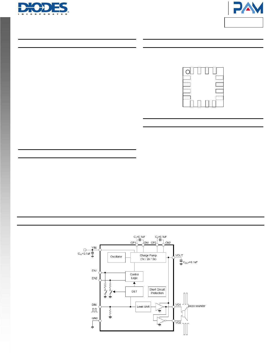
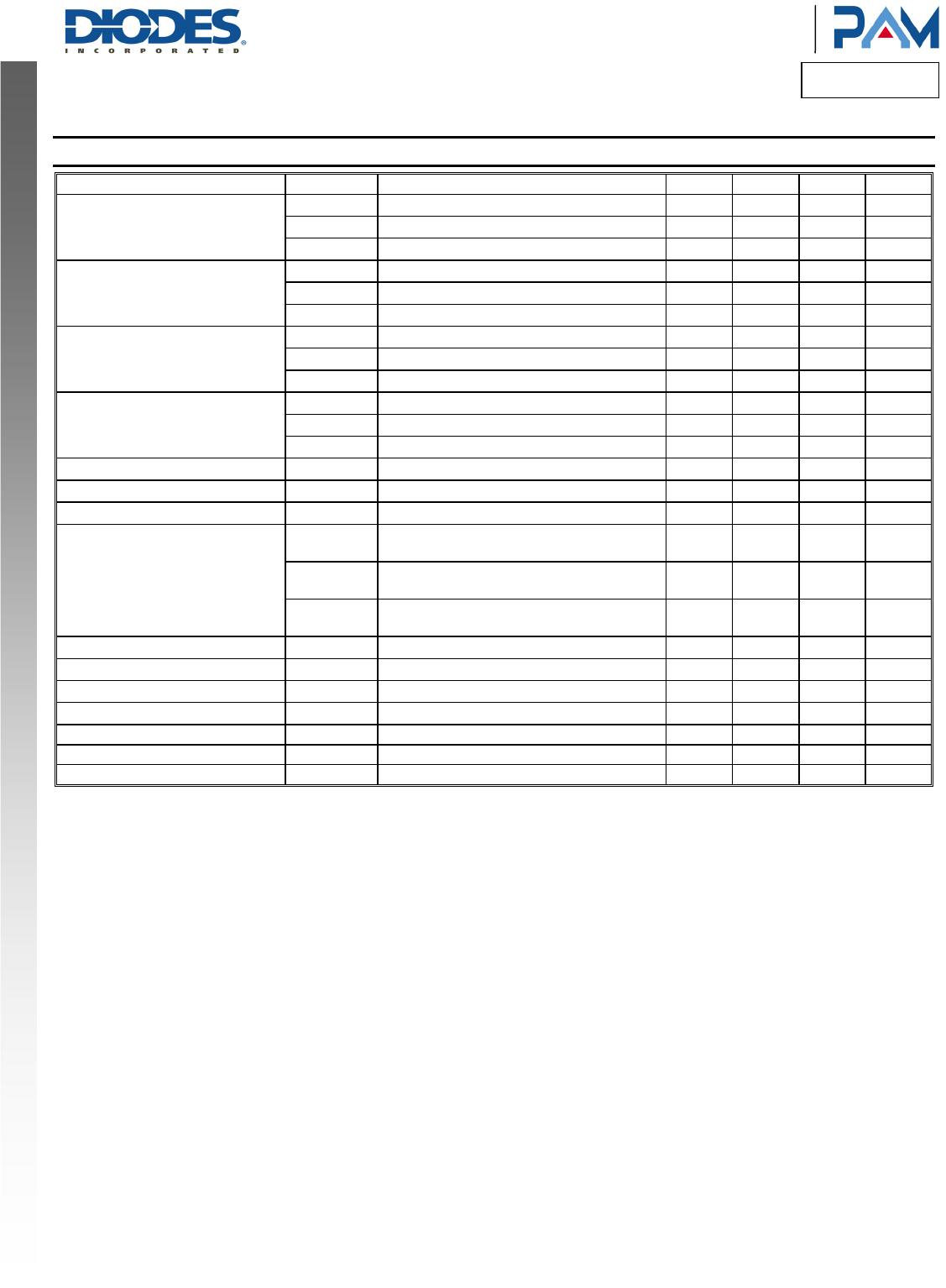
Electrical Characteristics (@T
A
= +25°C,VIN=3.0V, CPiezo=15nF, f
DIN
=4KHz, unless otherwise specified.)
Parameter Symbol Conditions Min Typ Max Unit
Output Voltage
V
OUT1
1x Mode 2.8 3 V
V
OUT2
2x Mode 5.2 6 V
V
OUT3
3x Mode 7.2 9 V
Operating Current 1
I
DD11
1x Mode, C
PIEZO
= No Load
50 µA
I
DD12
2x Mode, C
PIEZO
= No Load
720 µA
I
DD13
3x Mode, C
PIEZO
= No Load
1700 µA
Operating Current 2
I
DD21
1x Mode, Single-ended application 0.3 mA
I
DD22
2x Mode, Single-ended application 1.4 mA
I
DD23
3x Mode, Single- ended application 3.9 mA
Operating Current 3
I
DD31
1x Mode, Differential application 0.9 mA
I
DD32
2x Mode, Differential application 3.6 mA
I
DD33
3x Mode, Differential application 7.9 mA
Shutdown Current
I
SD
DIN = 0V 1 µA
Input Frequency
f
IN
Rectangular pulse 4 kHz
Oscillating Frequency
f
OSC
1 MHz
VOUT Start Delay Time
T
ON1
1x Mode, From DIN signal High to 90% V
OUT
steady state
270
µs
T
ON2
2x Mode, From DIN signal High to 90% V
OUT
steady state
320
µs
T
ON3
3x Mode From DIN signal High to 90% V
OUT
steady state
350
µs
Shutdown Delay Time
T
OFF
DIN = H- >L 42 ms
Output Short-circuit Current
I
SC
40 mA
Control Terminal Voltage H VIH EN1, EN2, DIN pins
0.8*V
IN
V
IN
V
Control Terminal Voltage L VIL EN1, EN2, DIN pins 0
0.2*V
IN
V
Control Terminal Current 1 IIH1 DIN = 3V 1 µA
Control Terminal Current 2 IIH2 VEN1, VEN2 = 3V,DIN = 3V 1 µA
Control Terminal Current 3 IIH3 VEN1, VEN2 = 3V, DIN = 0V 1 µA

PAM8904JPR

Mfr. #:
Manufacturer:
Diodes Incorporated
Description:
Audio Amplifiers Audio High Volt
Lifecycle:
New from this manufacturer.
Delivery:
DHL FedEx Ups TNT EMS
Payment:
T/T Paypal Visa MoneyGram Western Union

Products related to this Datasheet