TL431 family All information provided in this document is subject to legal disclaimers. © NXP Semiconductors N.V. 2015. All rights reserved.
Product data sheet Rev. 5 — 01 September 2015 6 of 27
NXP Semiconductors
TL431 family
Adjustable precision shunt regulator
6. Limiting values
[1] Device mounted on an FR4 Printed-Circuit Board (PCB), single-sided copper, tin-plated and standard
footprint.
[2] Device mounted on an FR4 PCB, single-sided copper, tin-plated, mounting pad for anode 1 cm
2
.
[3] Device mounted on a ceramic PCB, Al
2
O
3
, standard footprint.
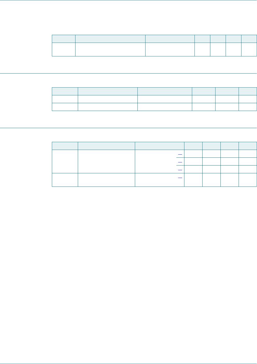
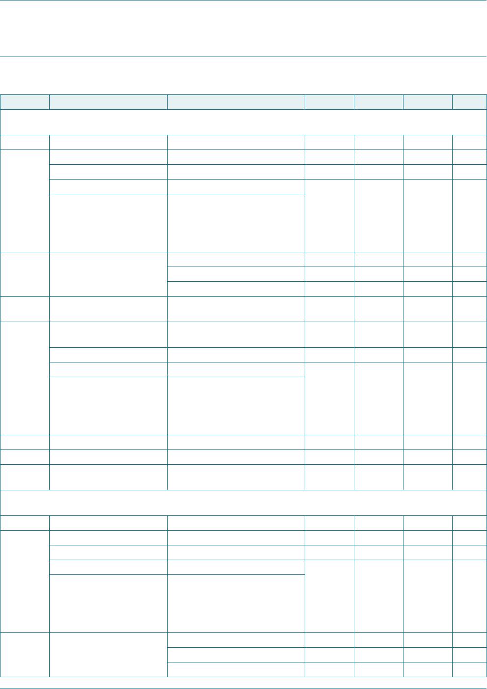
Table 6. Limiting values
In accordance with the Absolute Maximum Rating System (IEC 60134).
Symbol Parameter Conditions Min Max Unit
V
KA
cathode-anode voltage - 37 V
I
K
cathode current 100 150 mA
I
ref
reference current 0.05 10 mA
P
tot
total power dissipation T
amb
25 C
[1]
-350mW
[2]
-580mW
[3]
-950mW
T
j
junction temperature - 150 C
T
amb
ambient temperature
TL431XCDBZR 0 +70 C
TL431XIDBZR 40 +85 C
TL431XQDBZR
TL431XFDT
TL431XSDT
40 +125 C
T
stg
storage temperature 65 +150 C
(1) Ceramic PCB, Al
2
O
3
, standard footprint
(2) FR4 PCB, mounting pad for anode 1 cm
2
(3) FR4 PCB, standard footprint
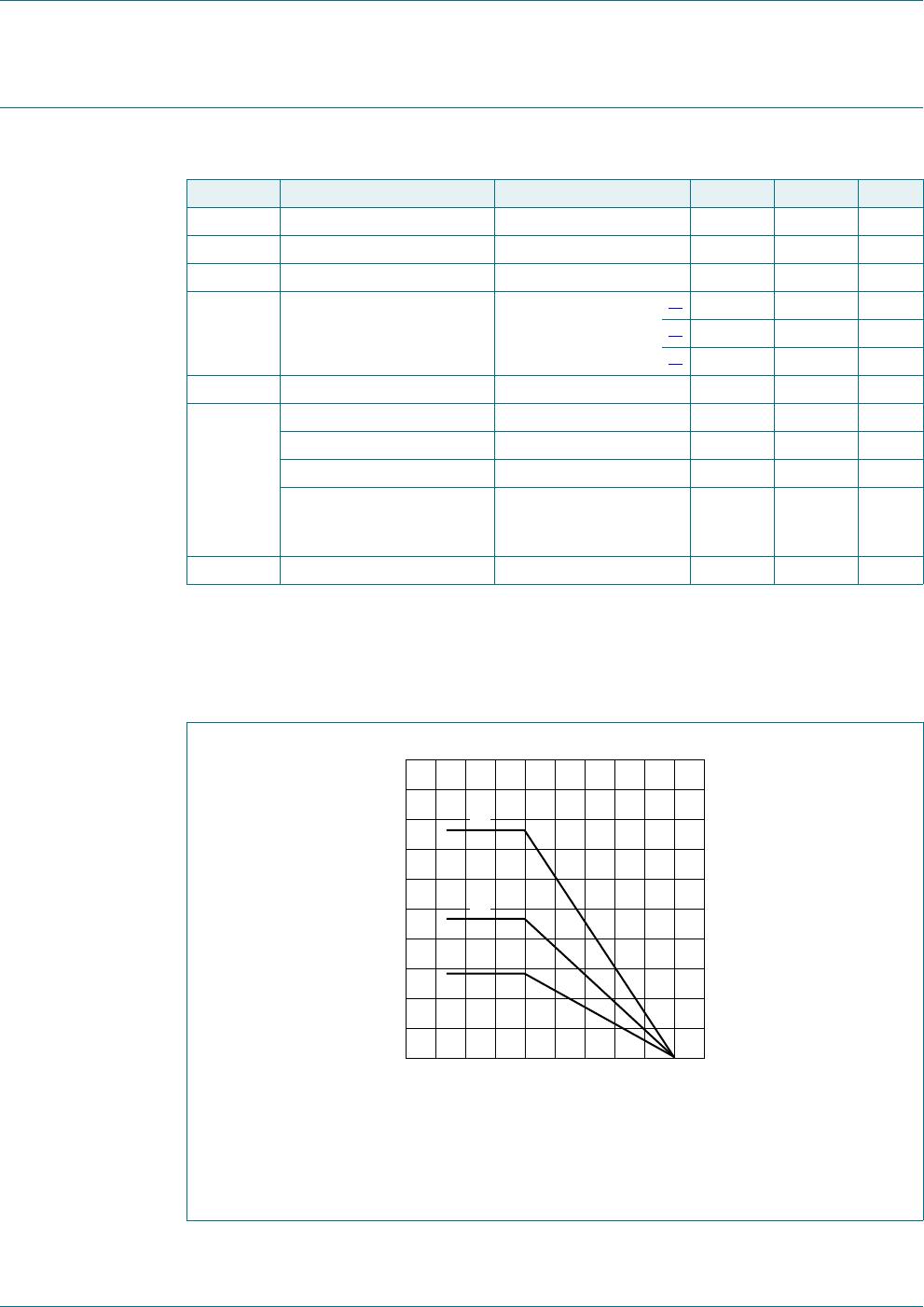
Fig 2. Power derating curves
T
amb
(°C)
75 17512525 7525
006aab570
500
750
250
1000
1250
P
tot
(mW)
0
(1)
(2)
(3)
TL431 family All information provided in this document is subject to legal disclaimers. © NXP Semiconductors N.V. 2015. All rights reserved.
Product data sheet Rev. 5 — 01 September 2015 7 of 27
NXP Semiconductors
TL431 family
Adjustable precision shunt regulator
7. Recommended operating conditions
8. Thermal characteristics
[1] Device mounted on an FR4 PCB, single-sided copper, tin-plated and standard footprint.
[2] Device mounted on an FR4 PCB, single-sided copper, tin-plated, mounting pad for anode 1 cm
2
.
[3] Device mounted on a ceramic PCB, Al
2
O
3
, standard footprint.
[4] Soldering point of anode.
Table 7. ESD maximum ratings
T
amb
=25
C unless otherwise specified.
Symbol Parameter Conditions Min Max Unit
V
ESD
electrostatic discharge voltage MIL-STD-883
(human body model)
-4kV
Table 8. Operating conditions
Symbol Parameter Conditions Min Max Unit
V
KA
cathode-anode voltage V
ref
36 V
I
K
cathode current 1 100 mA
Table 9. Thermal characteristics
Symbol Parameter Conditions Min Typ Max Unit
R
th(j-a)
thermal resistance from
junction to ambient
in free air
[1]
--360K/W
[2]
--216K/W
[3]
--132K/W
R
th(j-sp)
thermal resistance from
junction to solder point
[4]
--50K/W
TL431 family All information provided in this document is subject to legal disclaimers. © NXP Semiconductors N.V. 2015. All rights reserved.
Product data sheet Rev. 5 — 01 September 2015 8 of 27
NXP Semiconductors
TL431 family
Adjustable precision shunt regulator
9. Characteristics
Table 10. Characteristics
T
amb
=25
C unless otherwise specified.
Symbol Parameter Conditions Min Typ Max Unit
Standard-Grade (2 %):
TL431CDBZR; TL431IDBZR; TL431QDBZR; TL431FDT; TL431MFDT; TL431SDT; TL431MSDT
V
ref
reference voltage V
KA
=V
ref
; I
K
= 10 mA 2440 2495 2550 mV
V
ref
reference voltage variation V
KA
=V
ref
; I
K
=10mA
TL431CDBZR T
amb
=0Cto70C-616mV
TL431IDBZR T
amb
= 40 Cto85C - 14 34 mV
TL431QDBZR
TL431FDT
TL431MFDT
TL431SDT
TL431MSDT
T
amb
= 40 C to 125 C
V
ref
/V
KA
reference voltage variation
to cathode-anode voltage
variation ratio
I
K
=10mA
V
KA
=10VtoV
ref
- 1.4 2.7 mV/V
V
KA
=36Vto10V - 1 2mV/V
I
ref
reference current I
K
=10mA;
R1 = 10 k; R2 = open
-24A
I
ref
reference current variation I
K
=10mA;
R1 = 10 k; R2 = open
TL431CDBZR T
amb
=0Cto70C-0.41.2A
TL431IDBZR T
amb
= 40 Cto85C- 0.82.5A
TL431QDBZR
TL431FDT
TL431MFDT
TL431SDT
TL431MSDT
T
amb
= 40 C to 125 C
I
K(min)
minimum cathode current V
KA
=V
ref
-0.41mA
I
off
off-state current V
KA
=36V; V
ref
=0 - 0.1 1 A
Z
KA
dynamic cathode-anode
impedance
I
K
=1mAto100mA;
V
KA
=V
ref
; f < 1 kHz
-0.20.5
A-Grade(1%):
TL431ACDBZR; TL431AIDBZR; TL431AQDBZR; TL431AFDT; TL431AMFDT; TL431ASDT; TL431AMSDT
V
ref
reference voltage V
KA
=V
ref
; I
K
= 10 mA 2470 2495 2520 mV
V
ref
reference voltage variation V
KA
=V
ref
; I
K
=10mA
TL431ACDBZR T
amb
=0Cto70C-616mV
TL431AIDBZR T
amb
= 40 Cto85C - 14 34 mV
TL431AQDBZR
TL431AFDT
TL431AMFDT
TL431ASDT
TL431AMSDT
T
amb
= 40 C to 125 C
V
ref
/V
KA
reference voltage variation
to cathode-anode voltage
variation ratio
I
K
=10mA
V
KA
=10VtoV
ref
- 1.4 2.7 mV/V
V
KA
=36Vto10V - 1 2mV/V

TL431BCDBZRVL

Mfr. #:
Manufacturer:
Nexperia
Description:
Voltage References TL431BCDBZR/TO-236AB/REEL 11
Lifecycle:
New from this manufacturer.
Delivery:
DHL FedEx Ups TNT EMS
Payment:
T/T Paypal Visa MoneyGram Western Union