2
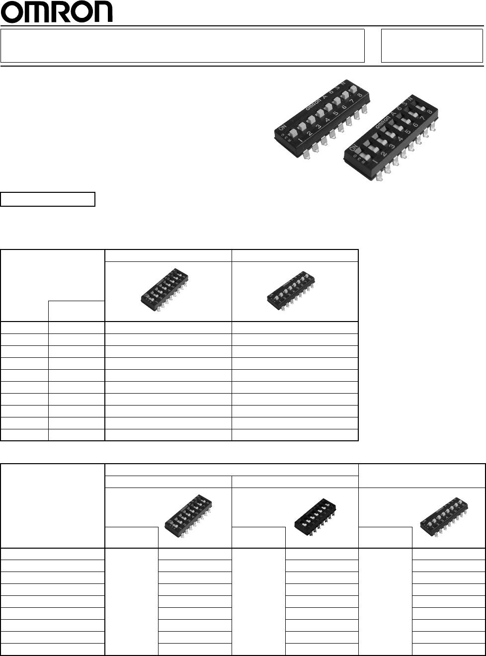
A6SNA6SN
■ Ratings/Characteristics
■ Dimensions (Unit: mm)
■ Internal Connections
Contact Form (Top View)
■ Precautions
Be sure to read the Safety precautions common to all DIP Switches for correct use.
Rating (resistive load)
25 mA at 24 VDC
10 μA (minimum current) at 3.5 VDC
Ambient operating temperature -30 to +85 °C at 60% max. (with no icing or condensation)
Ambient operating humidity 35% to 95% (at +5 to +35 °C)
Insulation resistance 100 MΩ min. (at 100 VDC with insulation tester)
Contact resistance (initial value) 200 mΩ max.
Dielectric strength Between terminals 300 VAC for 1 min
Vibration resistance Malfunction 10 to 55 Hz, 1.5-mm double amplitude
Shock resistance Malfunction
490 m/s
2
min.
Durability Electrical 1,000 operations min.
Washing Possible
Degree of protection IEC IP40
Operating force 0.98 to 7.9 N {100 to 806 gf}
Weight 0.3 g (2 poles) 0.55 g (4 poles) 0.8 g (6 poles) 1.05 g (8 poles) 1.3 g (10 poles)
ON
A6SN
7 8654321
0.8
±0.2
0.8
±0.2
1
1.6
0.6
0 to 0.2
0.25
1
7.5
1
Seal tape
(t=0.04)
1.1
P: Number of poles
2.54
1.2
1.6
0
−
0.2
0
−
0.2
0.6
0
−
0.1
0
−
0.1
Flat actuator
Standard
Raised actuator
Dimensions of PCB pad (Reference)
(Top View)
1 pole type
A
±
0.5
2.54× (P
−
1)
3.5
±0.15
4.35 to 4.55
9.3
±0.5
4.25
±0.15
4.48
±0.5
1.2
2.54× (P
−
1)
±0.1
6.1
10.4
7.5
Flat actuator
With seal tape
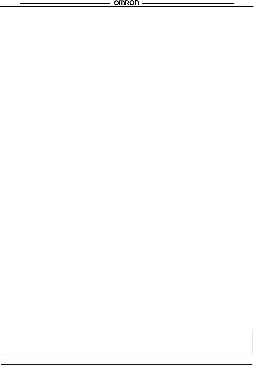
● Flat actuator
Standard / With seal tape
A6SN-
@101
A6SN-
@102-P
No.of
poles
Flat actuator
Raised actuator
A
Standard With seal tape
1 A6SN-1101 --- A6SN-1104 4.48
2 A6SN-2101 A6SN-2102-P A6SN-2104 7.0
3 A6SN-3101 A6SN-3102-P A6SN-3104 9.6
4 A6SN-4101 A6SN-4102-P A6SN-4104 12.1
5 A6SN-5101 A6SN-5102-P A6SN-5104 14.6
6 A6SN-6101 A6SN-6102-P A6SN-6104 17.2
7 A6SN-7101 A6SN-7102-P A6SN-7104 19.7
8 A6SN-8101 A6SN-8102-P A6SN-8104 22.3
9 A6SN-9101 A6SN-9102-P A6SN-9104 24.8
10 A6SN-0101 A6SN-0102-P A6SN-0104 27.3
● Raised actuator
A6SN-@104
A6SN-
@104-P