MAX6323/MAX6324
µP Supervisory Circuits with Windowed
(Min/Max) Watchdog and Manual Reset
4 _______________________________________________________________________________________
0
30
35
40
25
20
15
10
5
-40 200-20 40 60 80
MAX6323/24-01
TEMPERATURE (
°
C)
SUPPLY CURRENT vs. TEMPERATURE
SUPPLY CURRENT (µA)
V
CC
= 5.5V
V
CC
= 3.3V
V
CC
= 1.0V
0
30
20
5
-40 200-20 40 60 80
MAX6323/24-02
TEMPERATURE (
°
C)
POWER-DOWN RESET DELAY (µs)
POWER-DOWN RESET DELAY
vs. TEMPERATURE
V
OD
= 20mV
V
OD
= 100mV
25
15
10
0.9985
0.9990
0.9995
1.0000
1.0005
-40 200-20 40 60 80
MAX6323/24-04
TEMPERATURE (
°
C)
RESET THRESHOLD
NORMALIZED RESET THRESHOLD
vs. TEMPERATURE
0.9980
0.994
1.004
1.006
1.008
-40 200-20 40 60 80
MAX6323/24-05
TEMPERATURE (
°
C)
POWER-UP RESET TIMEOUT
NORMALIZED POWER-UP RESET TIMEOUT
vs. TEMPERATURE
1.002
1.000
0.998
0.996
0.992
1.004
1.002
1.000
0.998
1.006
1.008
-40 200-20 40 60 80
MAX6323/24-06
TEMPERATURE (
°
C)
NORMALIZED WATCHDOG TIMEOUT
PERIOD (FAST) vs. TEMPERATURE
NORMALIZED WATCHDOG TIMEOUT PERIOD (FAST)
0.996
0.994
0.995
1.000
1.001
0.999
0.997
0.998
0.996
1.002
1.003
-40 200-20 40 60 80
MAX6323/24-07
TEMPERATURE (°C)
NORMALIZED WATCHDOG TIMEOUT
PERIOD (SLOW) vs. TEMPERATURE
NORMALIZED WATCHDOG TIMEOUT PERIOD (SLOW)
0.992
1.004
1.002
1.000
1.006
1.008
-40 200-20 40 60 80
MAX6323/24-08
TEMPERATURE (°C)
NORMALIZED WATCHDOG OUTPUT PULSE WIDTH (µs)
NORMALIZED WATCHDOG OUTPUT
PULSE WIDTH vs. TEMPERATURE
0.998
0.996
0.994
V
OD
= V
TH
- V
CC
400
0
1 100 1000
MAXIMUM TRANSIENT DURATION
vs. RESET THRESHOLD OVERDRIVE
100
50
150
200
250
300
350
MAX6323/24-09
RESET COMPARATOR OVERDRIVE (mV)
MAXIMUM TRANSIENT DURATION (µs)
10
MAX632_AUT23
RESET ASSERTED
ABOVE THIS LINE
Typical Operating Characteristics
(V
CC
= full range, T
A
= +25°C, unless otherwise noted.)
40
120
100
80
60
140
160
-40 200-20 40 60 80
MAX6323/24-03
TEMPERATURE (
°
C)
MR TO RESET DELAY (ns)
MR TO RESET DELAY
vs. TEMPERATURE
20
0
MAX6323/MAX6324
µP Supervisory Circuits with Windowed
(Min/Max) Watchdog and Manual Reset
_______________________________________________________________________________________
5
500
µ
s/div
MAX6323/24-10
WDI
2V/div
2V/div
WDPO
FAST WATCHDOG TIMEOUT PERIOD
MAX6323AUT23
5ms/div
MAX6323/24-11
WDI
2V/div
2V/div
WDPO
SLOW WATCHDOG TIMEOUT PERIOD
MAX6323AUT23
Typical Operating Characteristics (continued)
(V
CC
= full range, T
A
= +25°C, unless otherwise noted.)
Pin Description
Active-Low. Reset is asserted when V
CC
drops below V
TH
and remains asserted until V
CC
rises above V
TH
for the duration of the reset timeout period. The MAX6323 has a push-pull output and the MAX6324 has an
open-drain output. Connect a pullup resistor from RESET to any supply voltage up to +6V.
Watchdog Pulse Output. The open-drain WDPO output is pulsed low for 1ms (typ) upon detection of a fast
or slow watchdog fault. WDPO is only active when RESET is high.
WDPO
5
RESET
6
Supply Voltage for the Device. Input for V
CC
reset monitor. For noisy systems, bypass V
CC
with a 500pF
(min) capacitor.
V
CC
4
Watchdog Input. The internal watchdog timer clears to zero on the falling edge of WDI or when RESET goes
high. If WDI sees another falling edge within the factory-trimmed watchdog window, WDPO will remain
unasserted. Transitions outside this window, either faster or slower, will cause WDPO to pulse low for 1ms
(typ).
WDI3
PIN
GroundGND2
Active-Low, Manual Reset Input. When MR is asserted low, RESET is asserted low, the internal watchdog
timer is reset to zero, and WDPO is reset to high impedance (open drain). After the rising edge of MR,
RESET is asserted for at least 100ms. Leave MR unconnected or connect to V
CC
if unused.
MR
1
FUNCTIONNAME
MAX6323/MAX6324
µP Supervisory Circuits with Windowed
(Min/Max) Watchdog and Manual Reset
6 _______________________________________________________________________________________
Detailed Description
The MAX6323/MAX6324 µP supervisory circuits main-
tain system integrity by alerting the µP to fault condi-
tions. In addition to a standard V
CC
monitor (for
power-on reset, brownout detect, and power-down
reset), the devices include a sophisticated watchdog
timer that detects when the processor is running out-
side an expected window of operation for a specific
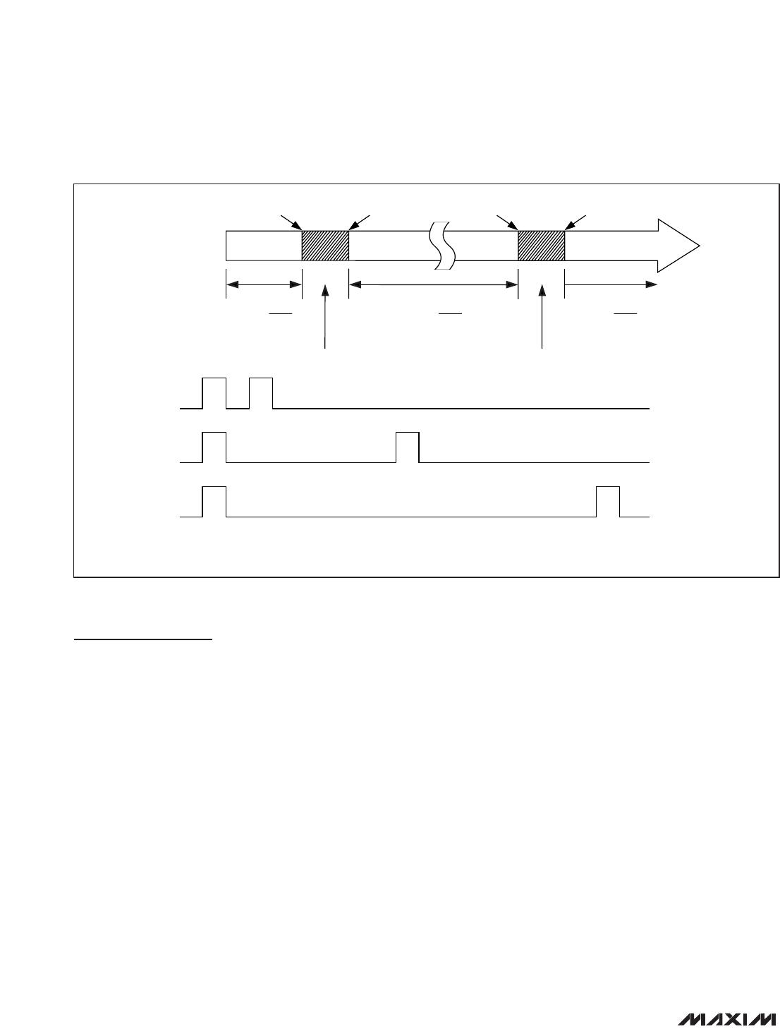
application. The watchdog signals a fault when the
input pulses arrive too early (faster than the selected
t
WD1
timeout period) or too late (slower than the select-
ed t
WD2
timeout period) (Figure 1). Incorrect timing can
lead to poor or dangerous system performance in tight-
ly controlled operating environments. Incorrect timing
could be the result of improper µP clocking or code
execution errors. If a timing error occurs, the
MAX6323/MAX6324 issue a watchdog pulse output,
independent from the reset output, indicating that sys-
tem maintenance may be required.
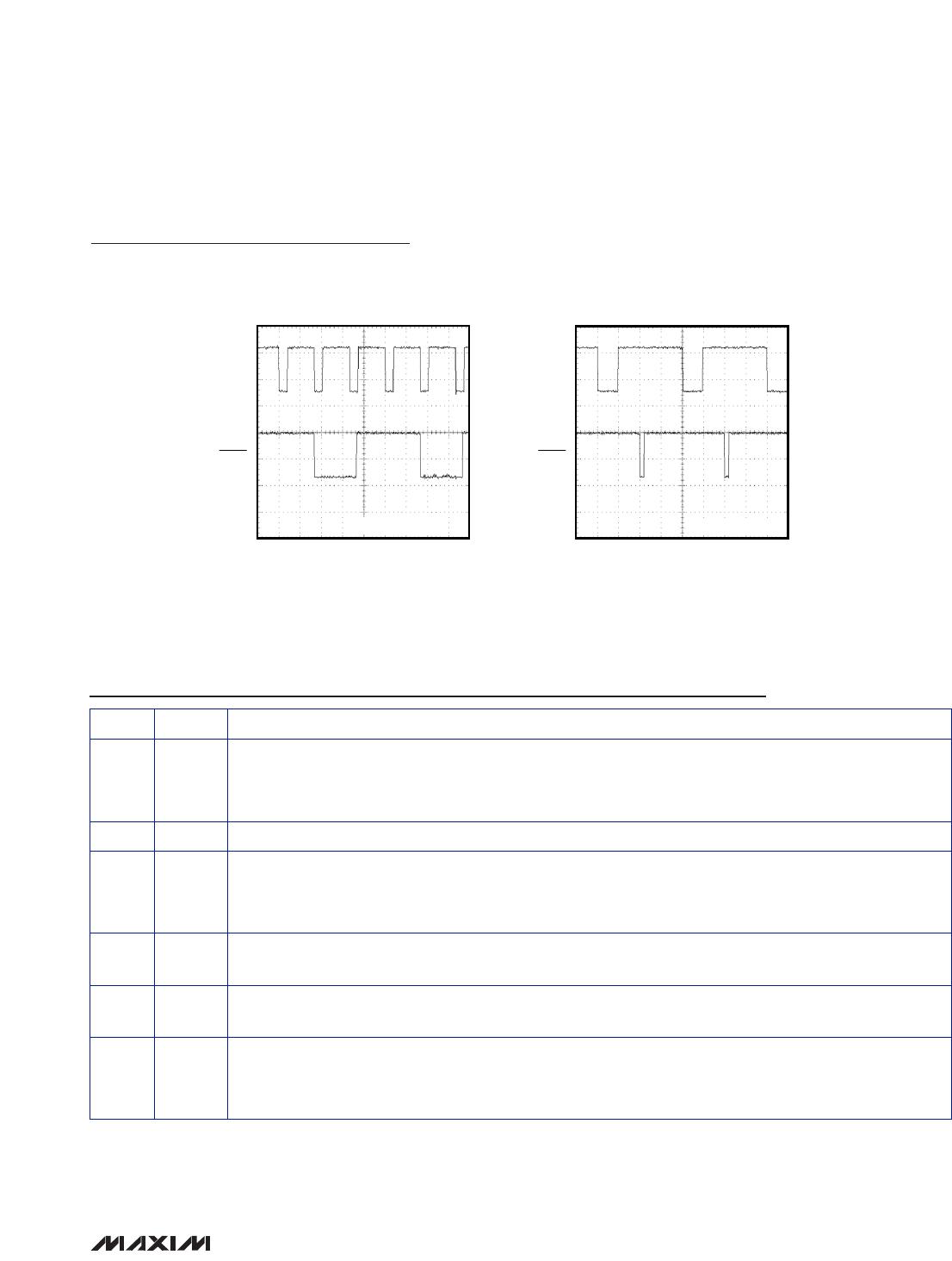
Watchdog Function
A pulse on the watchdog output WDPO can be trig-
gered by a fast fault or a slow fault. If the watchdog
input (WDI) has two falling edges too close to each
other (faster than t
WD1
) (Figure 2) or falling edges that
are too far apart (slower than t
WD2
) (Figure 3), WDPO is
pulsed low. Normal watchdog operation is displayed in
Figure 4 (WDPO is not asserted). The internal watch-
dog timer is cleared when a WDI falling edge is detect-
ed within the valid watchdog window or when the
device’s RESET or WDPO outputs are deasserted. All
WDI input pulses are ignored while either RESET or
WDPO is asserted. Figure 1 identifies the input timing
regions where WDPO fault outputs will be observed
with respect to t
WD1
and t
WD2
. After RESET or WDPO
deasserts, the first WDI falling edge is ignored for the
fast fault condition (Figure 2).
Upon detecting a watchdog fault, the WDPO output will
pulse low for 1ms. WDPO is an open-drain output.
Connect a pullup resistor on WDPO to any supply up to
+6V.
V
CC
Reset
The MAX6323/MAX6324 also include a standard V
CC
reset monitor to ensure that the µP is started in a known
state and to prevent code execution errors during
power-up, power-down, or brownout conditions.
RESET is asserted whenever the V
CC
supply voltage
*
UNDETERMINED STATES MAY OR MAY NOT GENERATE A FAULT CONDITION.
POSSIBLE STATES
GUARANTEED TO
ASSERT WDPO
GUARANTEED TO
ASSERT WDPO
GUARANTEED NOT TO
ASSERT WDPO
FAST FAULTCONDITION 1
SLOW FAULTCONDITION 3
NORMAL OPERATIONCONDITION 2
t
WD1
(min)
)
t
WD1
(max) t
WD2
(min) t
WD2
(max)
*
UNDETERMINED
*
UNDETERMINED
Figure 1. Detailed Watchdog Input Timing Relationship

MAX6324BUT46-T

Mfr. #:
Manufacturer:
Maxim Integrated
Description:
IC MPU/WATCHDG 15-100MS SOT23-6
Lifecycle:
New from this manufacturer.
Delivery:
DHL FedEx Ups TNT EMS
Payment:
T/T Paypal Visa MoneyGram Western Union