SMBJ Characteristics
Doc ID 5616 Rev 10 3/10
Table 3. Electrical characteristics - parameter values (T
amb
= 25 °C)
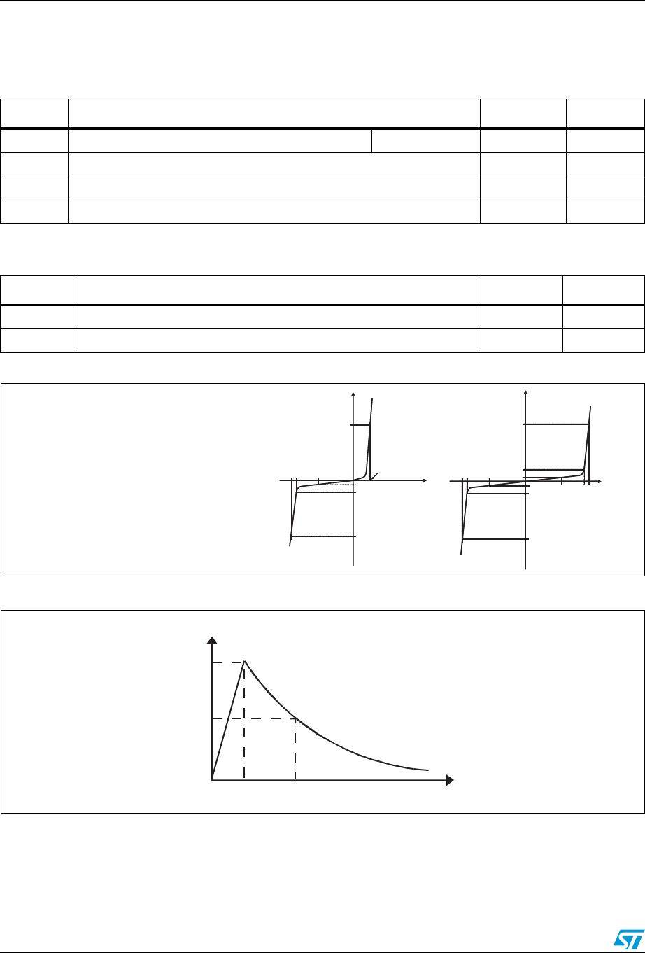
Order code
I
RM
max@V
RM
V
BR
@I
R
(1)
V
CL
@I
PP
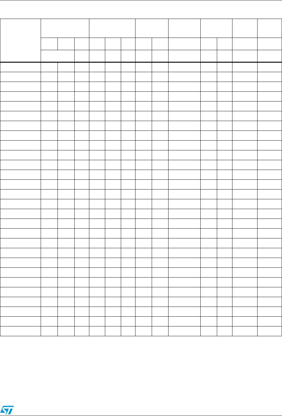
10/1000 µs
R
D
(2)
10/1000 µs
V
CL
@I
PP
8/20 µs
R
D
(2)
8/20 µs
αT
(3)
25 °C 85 °C min typ max max max
µA V V mA V A
(4)
Ω VA
(4)
Ω 10-4/ °C
SMBJ5.0A/CA 20 50 5.0 6.4 6.74 10 9.2 68 0.031 13.4 298 0.021 5.7
SMBJ6.0A/CA 20 50 6.0 6.7 7.05 10 10.3 61 0.048 13.7 290 0.022 5.9
SMBJ6.5A/CA 20 50 6.5 7.2 7.58 10 11.2 56 0.058 14.5 276 0.024 6.1
SMBJ8.5A/CA 20 50 8.5 9.4 9.9 1 14.4 41.7 0.096 19.5 205 0.044 7.3
SMBJ10A/CA 0.2 1 10 11.1 11.7 1 17 37 0.127 21.7 184 0.051 7.8
SMBJ12A/CA 0.2 1 12 13.3 14 1 19.9 31 0.168 25.3 157 0.068 8.3
SMBJ13A/CA 0.2 1 13 14.4 15.2 1 21.5 29 0.191 27.2 147 0.076 8.4
SMBJ15A/CA 0.2 1 15 16.7 17.6 1 24.4 25.1 0.236 32.5 123 0.114 8.8
SMBJ16A/CA 0.2 1 16 17.8 18.7 1 26 23.1 0.276 34.4 116 0.127 8.8
SMBJ18A/CA 0.2 1 18 20.0 21.1 1 29.2 21.5 0.328 39.3 102 0.168 9.2
SMBJ20A/CA 0.2 1 20 22.2 23.4 1 32.4 19.4 0.404 42.8 93 0.196 9.4
SMBJ22A/CA 0.2 1 22 24.4 25.7 1 35.5 17.7 0.481 48.3 83 0.257 9.6
SMBJ24A/CA 0.2 1 24 26.7 28.1 1 38.9 16 0.587 50 80 0.256 9.6
SMBJ26A/CA 0.2 1 26 28.9 30.4 1 42.1 14.9 0.683 53.5 75 0.288 9.7
SMBJ28A/CA 0.2 1 28 31.1 32.7 1 45.4 13.8 0.802 59 68 0.363 9.8
SMBJ30A/CA 0.2 1 30 33.3 35.1 1 48.4 13 0.888 64.3 62 0.443 9.9
SMBJ33A/CA 0.2 1 33 36.7 38.6 1 53.3 11.8 1.08 69.7 57 0.512 10.0
SMBJ36A/CA 0.2 1 36 40.0 42.1 1 58.1 10.3 1.35 76 52 0.611 10.0
SMBJ40A/CA 0.2 1 40 44.4 46.7 1 64.5 9.7 1.59 84 48 0.728 10.1
SMBJ48A/CA 0.2 1 48 53.3 56.1 1 77.4 8.1 2.28 100 40 1.03 10.3
SMBJ58A/CA 0.2 1 58 64.4 67.8 1 93.6 6.7 3.34 121 33 1.51 10.4
SMBJ70A/CA 0.2 1 70 77.8 81.9 1 113 5.5 4.91 146 27 2.22 10.5
SMBJ85A/CA 0.2 1 85 94 99 1 137 4.6 7.18 178 22.5 3.29 10.6
SMBJ100A/CA 0.2 1 100 111 117 1 162 3.8 10.3 212 19 4.69 10.7
SMBJ130A/CA 0.2 1 130 144 152 1 209 3 16.5 265 15 7.03 10.8
SMBJ154A/CA 0.2 1 154 171 180 1 246 2.4 23.8 317 12.6 10.2 10.8
SMBJ170A/CA 0.2 1 170 189 199 1 275 2.2 30.0 353 11.3 12.7 10.8
SMBJ188A/CA 0.2 1 188 209 220 1 328 2 48.5 388 10.3 15.2 10.8
1. Pulse test : t
p
< 50 ms
2. To calculate maximum clamping voltage at other surge level,use the following formula: V
CLmax
= V
CL
- R
D
x (I
PP
- I
PPappli
)
where I
PPappli
is the surge current in the application
3. To calculate V
BR
or V
CL
versus junction temperature, use the following formulas:
V
BR
@ T
J
= V
BR
@ 25°C
x (1 + αT x (T
J
– 25))
V
CL
@ T
J
= V
CL
@ 25°C
x (1 + αT x (T
J
– 25))
4. Surge capability given for both directions for unidirectional and bidirectional types.