L9935 Functional description
Doc ID 5198 Rev 10 19/29
5.12 Limitation of the diagnosis
The diagnosis depends on either detecting an overcurrent of more than typically 1.8 A
through the source transistor or on not detecting a flyback pulse, or on detecting severe
overcurrents of the sink transistor immediately after turn on.
● Small currents bypassing the load will not be detected.
● In the low current range (hold current) the flyback pulse (especially commutating
against the supply voltage after changing phase) may (depending on the inductivity of
the stepper motor windings) be too short to be detected correctly. For this reason
diagnosis using the flyback pulse is blanked at phase reversal at hold current.
● In the low current range (hold current) the current capability of the bridge is reduced on
purpose. Short to V
S
may not be detected. In stead the bridge may just chop like
normal operation.
● Flyback pulse detection is not blanked during PWM regulation at hold current (here
commutation voltage is less than 1V thus providing a longer pulse duration.) This
however should be taken in account using stepper motors with low inductivity (less than
0.5mH). Using motors with such a low inductivity the flyback voltage in hold mode may
decay too fast.
● Motors with extremely low ohmic resistance tend to pump up the current because
current decay during flyback approaches zero while at bridge turn on the current will
increase. This may lead to overcurrent detection. We suggest to use stepper motors
with an ohmic resistance of approximately 3 or more.
Partial shorts of windings or shorts of stepper motors with coils in series may still yield a
flyback pulses that are accepted by the diagnosis as a proper signal.
At stepping rates faster than 1ms/data transfer error flags indicating a short should be used
to initiate a pause of at least 1ms to allow the power bridges to cool down again.
5.13 Serial data interface (SPI)
The serial data interface itself consists of the pins SCL (serial clock), SDI (serial data input)
and SDO (serial data output).
To especially support bus controlled applications the additional signals
EN (chip enable not)
and CSN (chip select not) are available.
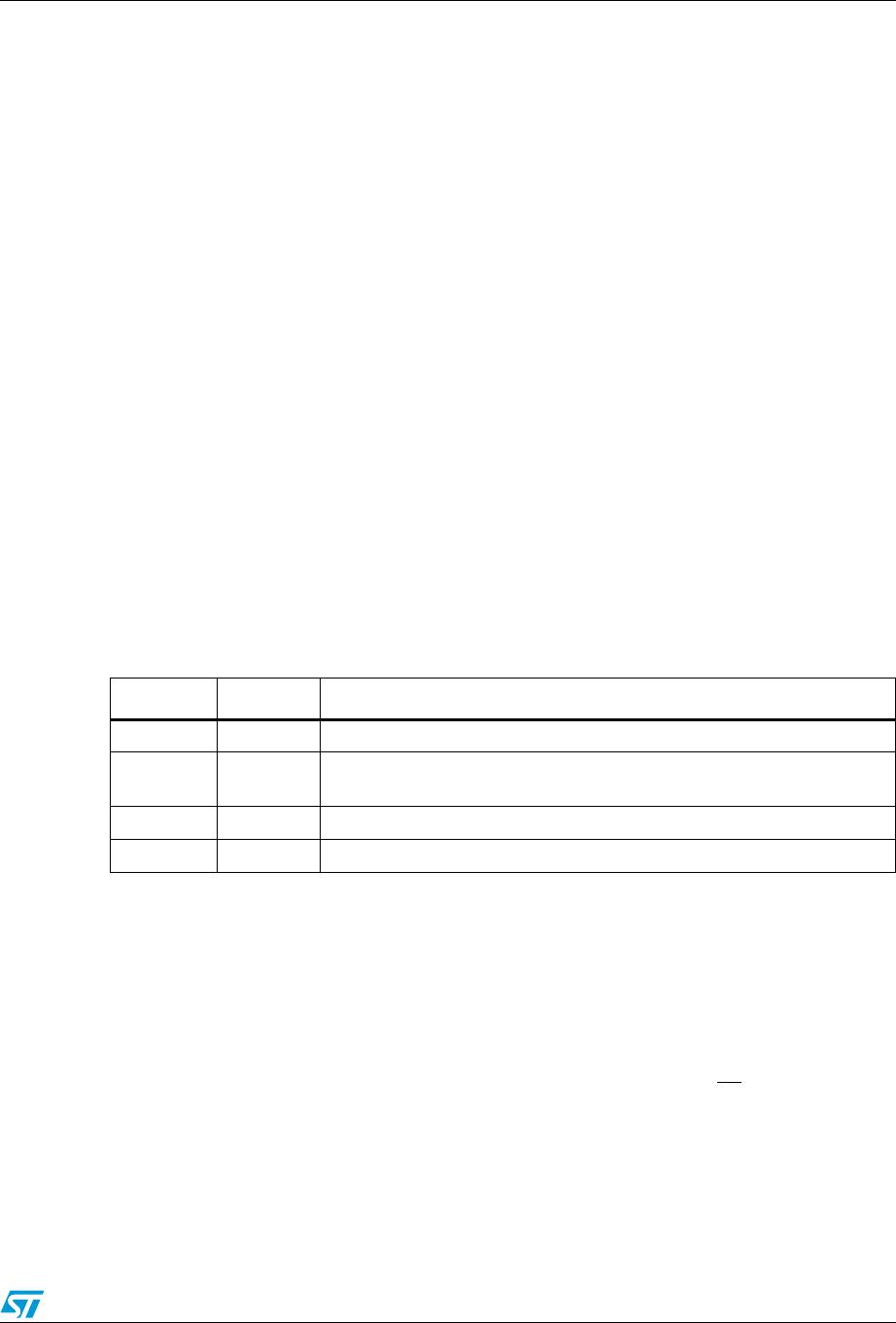
Table 8. Diagnosis description - bit7 and bit6
Error 1 bit7 Error 2 bit6 Description
H H Normal operation
L H
Short to VS (sink overload immediately after turn on) shorted load (no
flyback) open load (no flyback)
H L short to gnd (source overload, missing flyback is masked)
L L over temperature pre alarm

