NXP Semiconductors
PMEG2020EPAS
20 V, 2 A low VF MEGA Schottky barrier rectifier
PMEG2020EPAS All information provided in this document is subject to legal disclaimers. © NXP Semiconductors N.V. 2015. All rights reserved
Product data sheet 19 January 2015 9 / 15
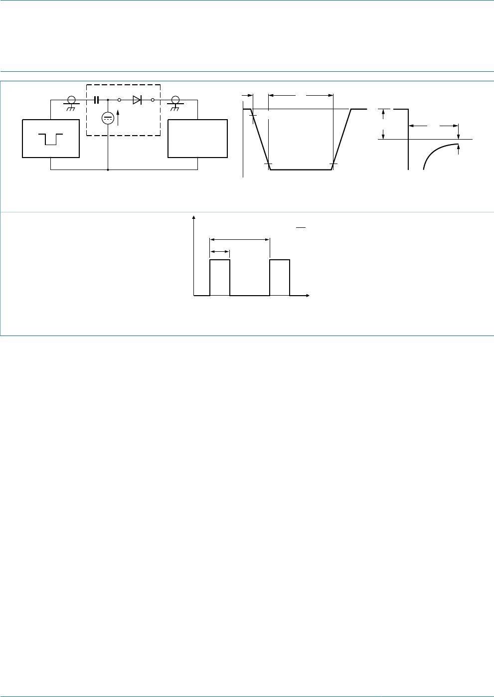
11. Test information
t
rr
(1)
+ I
F
t
output signal
t
r
t
p
t
10 %
90 %
V
R
input signal
V = V
R
+ I
F
× R
S
R
S
= 50 Ω
I
F
D.U.T.
R
i
= 50 Ω
SAMPLING
OSCILLOSCOPE
mga881
Fig. 14. Reverse recovery time: test circuit and waveforms
t
1
t
2
P
t
006aaa812
duty cycle δ =
t
1
t
2
Fig. 15. Duty cycle definition
The current ratings for the typical waveforms are calculated according to the equations:
I
F(AV)
= I
M
× δ with I
M
defined as peak current, I
RMS
= I
F(AV)
at DC, and I
RMS
= I
M
× √δ with
I
RMS
defined as RMS current.
11.1 Quality information
This product has been qualified in accordance with the Automotive Electronics Council
(AEC) standard Q101 - Stress test qualification for discrete semiconductors, and is
suitable for use in automotive applications.

