4
Table 1
The 1 MHz idle signal described in the IEEE 802.3
10Base-FL standard assures that the burst-mode proto-
col used for copper wire Ethernet is converted to a pro-
tocol that will optimize the performance of a fiberoptic
receiver. More details about inexpensive fiberoptic
solutions suitable for use with higher-efficiency block
substitution codes, such as 4B5B, and 8B10B, can be
found in Avago Technologies Application Notes 1122
and 1123. This publication will stay focused on solutions
compatible with unencoded data, because many system
designers need a fiberoptic solution that can use proto-
cols originally developed for use with copper wires.
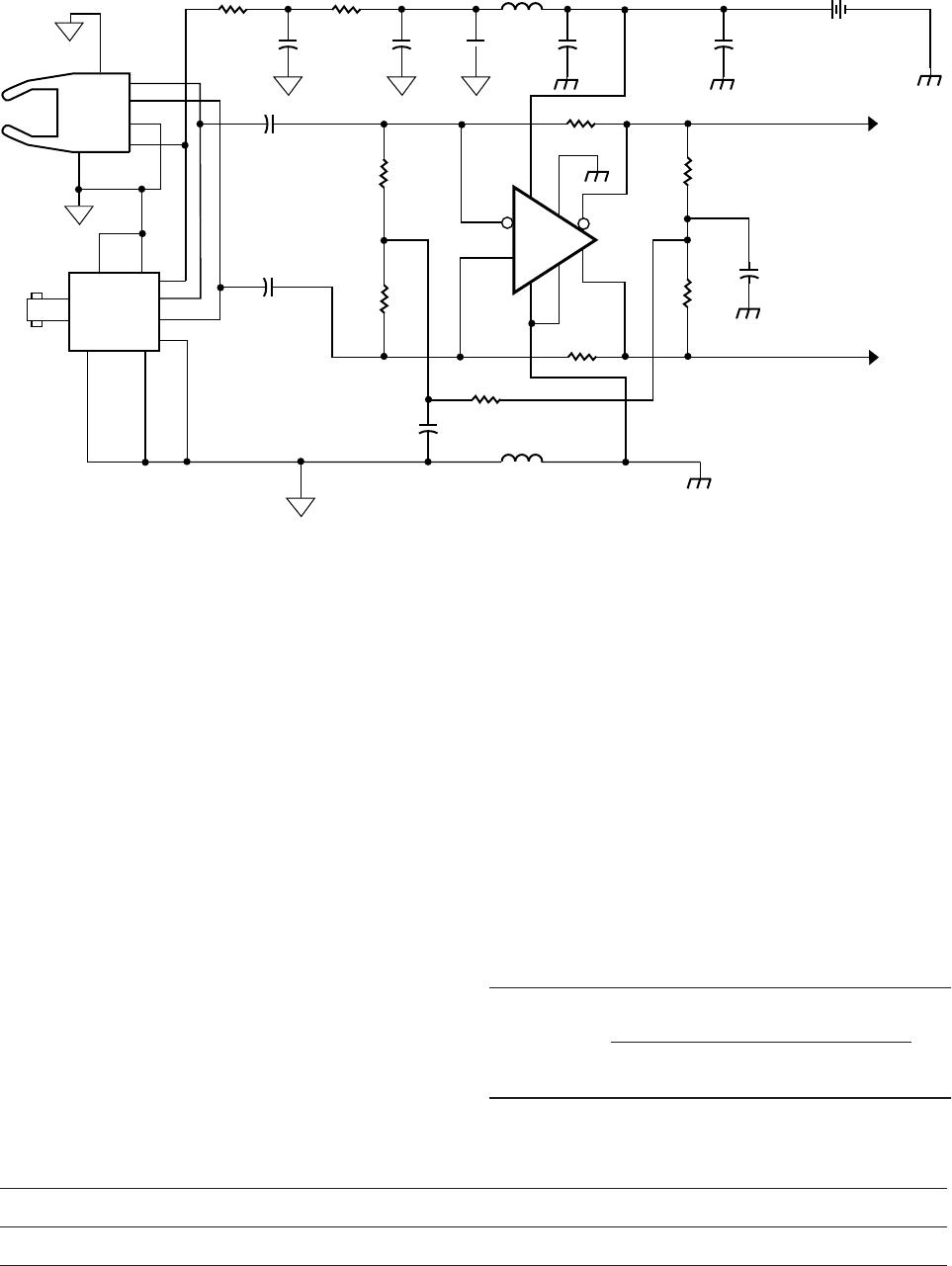
Distances and Data Rates Achievable
The simple transceivers recommended in this applica-
tion note can be used to address a very wide range
of distances, data rates, and system cost targets. The
maximum distances allowed with various types of
optical fiber when using Avago Technologies’ wide
range of fiberoptic transceiver components are shown
Table 1. One simple calculation is needed to optimize
the receiver for use at the desired maximum symbol rate
of your system application. No transmitter or receiver
adjustments are needed when using fiber cable length
that vary from virtually zero length up to the maximum
distances specified in Table 1.
Transmitter
Component Part #
and Wavelength
Receiver
Component Part #
and Wavelength
Fiber Diameter
Type
Maximum Distance at 32 MBd
with the transceiver circuits
recommended in this publication
HFBR-15X7Z
650 nm LED
HFBR-25X6Z
650 nm
1 mm plastic
step index
27 meters with transmitter in Fig. 3
and receiver in Fig. 4
HFBR-15X7Z
650 nm LED
HFBR-25X6Z
650 nm
1 mm plastic
step index
42 meters with transmitter in Fig. 3
and receiver in Fig. 5
HFBR-15X7Z
650 nm LED
HFBR-25X6Z
650 nm
200 mm
HCS step index
690 meters with transmitter in Fig. 3
and receiver in Fig. 4
HFBR-15X7Z
650 nm LED
HFBR-25X6Z
650 nm
200 mm
HCS step index
1.0 kilometer with transmitter
in Fig. 3 and receiver in Fig. 5
HFBR-14X2Z
820 nm LED
HFBR-24X6Z
820 nm
200 mm
HCS step index
690 meters with transmitter in Fig. 3
and receiver in Fig. 4
HFBR-14X2Z
820 nm LED
HFBR-24X6Z
820 nm
200 mm
HCS step index
1.0 kilometer with transmitter
in Fig. 3 and receiver in Fig. 5
HFBR-14X4Z
820 nm LED
HFBR-24X6Z
820 nm
62.5/125 mm
multimode glass
800 meters with transmitter in Fig. 3
and receiver in Fig. 4
HFBR-14X4Z
820 nm LED
HFBR-24X6Z
820 nm
62.5/125 mm
multimode glass
1.6 kilometers with transmitter
in Fig. 3 and receiver in Fig. 5
HFBR-13X2TZ
1300 nm LED
HFBR-23X6TZ
1300 nm
62.5/125 mm
multimode glass
1.3 kilometers with transmitter
in Fig 3. and receiver in Fig. 4
HFBR-13X2TZ
1300 nm LED
HFBR-23X6TZ
1300 nm
62.5/125 mm
multimode glass
3.3 kilometers with transmitter
in Fig. 3 and receiver in Fig. 5
5
1
2
3
4
5
8
U2A
HFBR-15X7Z
2
7
3
6
4
5
8
1
U2B
HFBR-14X4Z
U1C
74ACTQ00
C1
0.1 mF
8
6
3
10
14
9
U1B
74ACTQ00
5
4
U1A
74ACTQ00
U1D
74ACTQ00
2
1
11
13
12
L1
TDK
#HF30ACB453215
+5 V
HOST
SYSTEM POWER
C2
10 mF
V
cc
7
GND
TTL IN
C3
R1
R2
R3
Transmitter
HFBR-15X7Z
650 nm LED
HFBR-14X4Z
820 nm LED
HFBR-13X2TZ
1300 nm LED
Fiber Type 1 mm Plastic
200 mm HCS 62.5/125 mm 62.5/125 mm
R1
120 W 33 W 33 W 22 W
R2
120 W 33 W 33 W 27 W
R3
390 W 270 W 270 W
C3 82 pF 470 pF 75 pF 150 pF
Table 2
Simple TTL Compatible LED Transmitter
A high-performance, low-cost TTL-compatible trans-
mitter is shown in Figure 3. This transmitter recom-
mendation is deceptively simple, but has been highly
developed to deliver the best performance achievable
with Avago Technologies’ LED transmitters. The recom-
mended transmitter is also very inexpensive, because
the 74ACTQ00 gate used to current modulate the LED
can typically be obtained for under $0.40. No calcula-
tions are required to determine the passive component
needed when using various Avago Technologies’ LEDs
with a wide range of optical fibers. Simply use the
recommended component values shown in Table 2,
and the transmitter shown in Figure 3 can be used to
address a broad range of applications.
Simple TTL Compatible Receiver
A very simple TTL-compatible receiver that has ad-
equate sensitivity for a wide range of applications is
shown in Figure 4. Equation 1 allows the designer to
quickly determine the values of C6 and C7 so that the
receiver is optimized for operation at any data rate up to
a maximum of 32 MBd.
Figure 3. TTL-Compatible LED Transmitter
6
1
2
3
4
5
8
U3A
HFBR-25X6Z
2
7
3
6
4
5
8
1
U3B
HFBR-24X6Z
C5
0.1 mF
C7
+5 V
NOISY HOST
SYSTEM POWER
C6
R4
4.7
C9
0.1 mF
C10
10mF
C11
0.1mF
C12
10 mF
R5
4.7
L2
COILCRAFT 1008LS-122XKBC
+
TTL OUT (-)
R10
240
R11
240
C13
0.1 mF
TTL OUT (+)
R12
2.2 k
R9
120 k
R6
270
U4
LT1016CS8
R7
270
C8
0.1 mF
L3
COILCRAFT 1008LS-122XKBC
+
3
2
4
6
7
8
5
1
R8 120 k
Figure 4. Simple Fiberoptic Reciver for use with DC to 32 MBd Arbitary Duty Factor Data
Receiver HFBR-25X6Z – 650 nm HFBR-24X6Z – 820 nm HFBR-23X6TZ – 1300 nm
Fiber Type 1 mm Plastic
200 mm HCS 62.5/125 mm 62.5/125 mm
Table 3
Equation 1
C6 = C7 =
2
(3) (R6 + R7) [ Data Rate (Bd) ]
Enhanced TTL Compatible Receiver
The receiver circuit shown in Figure 5 is suitable for
use in applications that require greater optical cable
lengths. The receiver in Figure 5 provides 6 dB more
receiver sensitivity than the simplified receiver shown
in Figure 4. Equation 2 allows the designer to quickly
determine the values of C9 and C10 so that the receiver
is optimized for operation at any data rate up to a maxi-
mum of 32 MBd.
Printed Circuit Artwork
The performance of transceivers that use Avago
Technologies fiberoptic components are partially
dependent on the layout of the printed circuit board on
which the transceiver circuits are constructed. System
designers are encouraged to embed the printed circuit
designs provided in this application note to achieve the
fiberoptic link performance described in Table 1. The
printed circuit artwork in Figure 6 is for the transmitter
in Figure 3 and the receiver in Figure 4. The printed
circuit artwork in Figure 7 is for the transmitter in Figure
3 and the receiver in Figure 5. Electronic copies of the
Gerber files for the artwork shown in this application
note can be obtained by using the Internet to down-
load the printed circuit designs.
To obtain the artwork for the transmitter shown in
Figure 3 and the receiver shown in Figure 4, download
file from the following URL: http://www.avagotech.com
To obtain the artwork for the transmitter shown in
Figure 3 and the receiver shown in Figure 5, download
file from the following URL: http://www.avagotech.com

HFBR-0536

Mfr. #:
Manufacturer:
Broadcom / Avago
Description:
Fiber Optic Development Tools 32MBd Data Comm Evaluation Kit
Lifecycle:
New from this manufacturer.
Delivery:
DHL FedEx Ups TNT EMS
Payment:
T/T Paypal Visa MoneyGram Western Union

Products related to this Datasheet